MESH |
Generating a mesh is the process where a finite element mesh is calculated from the geometry definition. This mesh will be used for the FEM analysis in a later step. Conditions (see section Conditions) and materials (see section Materials) assigned to geometric entities will be transferred to the nodes and elements of the new mesh.
What is meshed and how, is controlled by some default options which can be changed with the commands described later.
The generation does not depend on the state ON/OFF of the layers at the moment of the
generation (see section Layers), but frozen layers are not meshed if the preference
NoMeshFrozenLayer is selected (see section Preferences->Meshing).
Every node and element will be assigned to the layer in which the original geometrical entity was defined.
Defaults are:
- An entity is meshed if does not belong to a higher level entity.
- A line mesh is made of two-noded elements and a surface mesh is made of non-structured triangular elements. The default for structured meshes are quadrilateral elements. Unstructured volume meshes are composed by non-structured tetrahedral elements, structured volume meshes are composed by hexahedra and Semi-structured volume meshes are composed by prisms.
All these default elements use linear interpolations for the unknown variables.
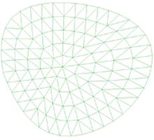
Unstructured |
![]()
Size is given by the average side (edge) of the corresponding mesh element.
It is possible to assign different sizes to different entities of the mesh. This means that in the vicinity of these entities, the generated elements will be approximately of that size. All the entities that have not an assigned size when meshing, take the default one. Points do not take any size if none is given to them.
To assign a size of 0.0 to an entity is the same as setting the default size.
The transition between different sizes is controlled by a parameter in
preferences (see section Preferences->Meshing).
![]()
Option By chordal error asks the user for a chordal error (the maximum distance between the generated
element and the real geometry) and also a minimum and a maximum
size limits. GiD assigns the corresponding sizes to
all the entities to accomplish this condition. It will only change the
current sizes if the new one is smaller than the previously defined. In
structured surfaces, stretching is permitted. It means that if
necessary, elements can have very different size along both principal
directions.
Note: It is assigned to entities a size between the minimum and maximum; however, when generating the mesh, GiD adapts the size of the elements only if necessary, exceeding sometimes the minimum and maximum limits.
Assign sizes by chordal error window
In this window the effect of different chordal error values over the number
of elements that will be created over a line can be viewed. Any line of
the geometry can be picked up and be used in this window.
![]()
When option Correct sizes is selected, a window appears. In this window it is possible to enter a minimum and a maximum mesh size.
Correct meshing sizes window
If option By geometry is activated, sizes are assigned to all the entities depending on the shape of the geometry. This means that smaller surfaces will have smaller elements.
If option Correct incompatible sizes is activated, some sizes are reduced in order to control that the transitions between sizes in close entities are not too fast.
It will only change the existing sizes if the new size is smaller than that previously defined.
Note: Applying last two options with default values is the same than setting the preference Automatic correct sizes to Normal in the preferences window (see section Preferences).
Note: To mesh a difficult volume trying to adjust element sizes to geometry detail, it may be useful to use By geometry and Correct incompatible sizes options setting the larger size equal to the default size for meshing, and the smaller size reflecting the details ( 10 times smaller, for example). Sometimes it is also necessary to assign sizes by cordal error.
![]()
The format of the file containing the background mesh is the following:
- First line:
BackgroundMesh V 1.0 - Description of the mesh. The format of that mesh is described in the Mesh read section (see section GiD mesh).
- Desired sizes in the following format:
DesiredSize (Nodes or Elements)
  number of        size
  node/element
...
Background mesh file example:BackgroundMesh V 1.0 MESH dimension 2 ElemType Triangle Nnode 3 Coordinates 1 5.61705 4.81504 0.00000 ... 51 -5.64191 -1.53335 0.00000 end coordinates Elements 1 24 16 26 2 16 10 14 ... 76 34 31 28 end elements DesiredSize Elements 1 0.20000 2 0.20000 ... 75 1.50000 76 1.50000 End DesiredSize
This option is used to assign Unstructured mesh to geometrical entities (lines, surfaces
or volumes). Using this option it's not necessary to specify an unstructured size to entities.
The default size will be set to them.
CAUTION: Be careful when assigning big sizes to entities close to others where a small size has been given. It may be impossible to obtain a mesh.
CAUTION: When using contact elements (see section Contact surface creation and see section Contact volume creation), the same size must be used for contact and for duplicate entities.
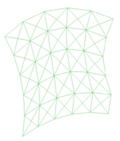
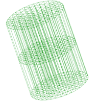
Structured |
![]()
A structured mesh is defined as a mesh where all the nodes have the same number of elements around it.
The size of the elements is defined in a different way than for a non-structured mesh. In this case, the mesh is not defined by the size but by the number of elements that are required on every line. This number must be the same for all lines that are opposite to each other on each surface. When meshing volumes, this definition must be the same for opposite surfaces.
To create a structured mesh, choose structured and volumes,
surfaces or lines. After choosing escape,
the number of elements per line is given.
Later, lines can be selected and related lines (in option surface or volume),
are added or deleted from the group. This process can be repeated as many times
as necessary until all lines have a new value.
Lines with no numbering given will
have two elements over them. All no selected lines will also have two elements by
default.
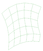
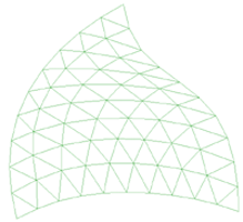
In case of surfaces, structured mesh can be 4-sided, 3-sided or centered structured.
@c
Four-sided structured surface mesh |
Three-sided structured surface mesh |
Centered structured surface mesh |
By default, the generated elements in 4-sided structured meshes
are quadrilateral, but they can be triangles. In this case triangles
can be symmetrical or non-symmetrical (see section Preferences->Meshing).
Symmetrical structured triangle mesh |
Non-symmetrical structured triangle mesh |
Four-sided structured mesh can be done in 4-sided surfaces or NURBS surfaces.
Three-sided structured mesh (related to a three sided surface) and centered structured mesh
can only be meshed with triangles.
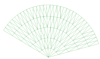
Centered structured meshes can be centered in an interior point of the surface, or in a point
located in the surface boundary with the opcion Set center. Is user doesn't set a center
GiD will locate it automatically.
Centered structured mesh whith center inside the surface |
Centered structured mesh whith center in the surface boundary |
When selecting this kind of structured mesh (centered), the following window appears to introduce the number of concentric and perimetral divisions, as the two weights to concentrate elements in the structured center or in the boundary.
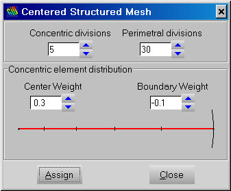
Centered structured meshing window
In case of volumes, structured mesh can be 6-sided, with three-sided structured mesh in tops,
or with centered structured mesh in tops (all types
are obtained selecting structured and volumes).
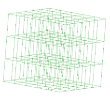
Six-sided structured volume mesh |
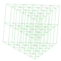
Structured volume mesh with three-sided structured surface mesh in tops |
Structured volume mesh with centered structured surface mesh in tops |
By default, the generated elements in 6-sided structured volume meshes will be hexahedra,
but they can be tetrahedra or prisms. In case of tetrahedra, they
can be symmetrical or non-symmetrical (see section Preferences->Meshing).
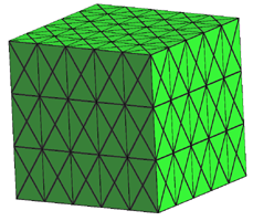
Symmetrical structured tetrahedra mesh |
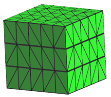
Non-symmetrical structured tetrahedra mesh |
In case of centered structured or three-sided surface in tops, the default element type is prism, but user can also choose tetrahedra.
In case of 6-sided structured volume mesh, volumes must have 6 contour surfaces.
It is possible to mix some entities with structured meshes and others with unstructured ones.
To convert a structured entity to a non-structured one, select reset (see section Reset mesh data) or assign unstructured mesh to it (see section Unstructured).
To change the default element type See section Element type.
Note 1: One NURBS surface can be structured with any number of contour lines but must have a good shape form. This means that it must have 4 big angles and the other angles must be small. With this criterion, the shape will be topologically similar to one quadrilateral.
Note 2: When assigning structured divisions to on line or with difficult topology, GiD may need to reassign some sizes to make the structured mesh conformal. It will be done automatically. If it is impossible to create compatibility between surfaces, a message is given.
Note 3: It is possible to assign a number of structured divisions to the boundary line of a surface or volume, and then create an unstructured mesh for the surface/volume.
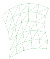
Structured concentrate |
![]()
By default, all partitions in one structured line have the same approximate length.
This command lets the user select one line. Then, in the graphical window the sense
of the line is shown with one arrow. The user will enter a positive or negative weight.
If the weight is positive the size of the elements will be concentrated at the extreme
of the line, if negative, the elements will be repelled.
As the magnitude of the weight increases, the difference between element sizes will be bigger.
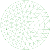
SemiStructured |
![]()
A semi-structured mesh is a mesh that is structured only in one direction of the volume. This kind of mesh have only sense in prismatic volumes, where it can be identified two top surfaces and lateral ones. This kind of mesh parts from top surfaces meshes, that are topologically identycally, and it is structured in the prismatic direction. It's not necessary to mesh top surfaces as structured ones, and depending on the element type selected in each volume surface, volume elements will be hexahedra, prism or tetrahedra.
Note 1: When assigning divisions in structured direction, GiD may need to reassign some sizes to make the structured mesh conformal with the surronding ones. It will be done automatically. If it is impossible to create compatibility between surfaces, a message is given.
Set Master surface or Structured direction:
Structured direction of the prismatic volume can be set by using this option. If no structured direction is set, GiD will assign it automatically. This option takes sense in case of volumes that are prismatic in more than one direction, where user may want an specific structured direction and not another one.
In SemiStructured volumes (as they are prismatic) it can be distinguished two top surfaces.
They will have topologically identycal meshes, so one of them is obtained from the other.
The Master surface is the one that is meshed first, so its mesh will determine the topology
of both top surfaces meshes.
By selecting Set->Master surface it can be forced one top surface to be the Master one, and
the structured direction is set automatically.
Quadratic |
![]()
Option Quadratic applies to all the elements of the problem. If chosen,
elements will be:
- Linear: 3 nodes.
- Triangle: 6 nodes.
- Quadrilateral: 8 nodes.
- Tetrahedra: 10 nodes.
- Hexahedra: 20 nodes.
- Prisms: 15 nodes.
Option Quadratic9 is similar to option Quadratic, but will
generate 9-noded Quadrilaterals and 27-noded Hexahedra.
Element type |
![]()
With this command, the type of element desired is selected. It is only necessary to do this when the element type is different from the default (see section MESH).
Types are:
- Default: for surfaces and volumes. This option lets GiD to assign compatible element type to geometric entities, assigning the default ones if it is possible (see section MESH).
- Linear: for lines.
- Triangle and Quadrilateral: for surfaces.
- Tetrahedron, Prism and Hexahedron: for volumes.
- Only points: Just for volumes. Point elements are generated.
- Linear and Quadrilateral: for contact surfaces.
- Linear, Prism and Hexahedron: for contact volumes.
By default, the elements are of minimum order: 3-noded triangle,
4-noded quadrilateral and so on. To increase the degree, use command
Quadratic (see section Quadratic). Option Quadratic
applies to all the elements of the problem.
Point: 1 node,Point connectivity: 
Linear: 2 or 3 nodes,Line connectivities: 

Triangle: 3 or 6 nodes,Triangle connectivities: 

Quadrilateral: 4, 8 or 9 nodes,Quadrilateral connectivities: 


Tetrahedra: 4 or 10 nodes,Tetrahedral connectivities: 
Hexahedra: 8, 20 or 27 nodes.Hexahedral connectivities: 
Prism: 6 or 15 nodes,Prism connectivities: 
The Linear option assures, not only the meshing of lines, but also the
creation of 2-node contact lines between surfaces or volumes, if desired.
At contact surfaces, GiD elements are:
- Linear: 2 or 3 nodes.
- Triangle: 3 or 6 nodes.
- Quadrilateral: 4, 8 or 9 nodes.
At contact volumes (and separated contacts), elements are:
- Linear: 2 or 3 nodes.
- Prism: 6 or 15 nodes.
- Hexahedron: 8, 20 or 27 nodes.
To decide what parts of the geometry should be meshed use command: See section Mesh criteria.
Mesh criteria |
![]()
GiD provides five different criteria to generate the mesh.
The Default option skips meshing the boundaries, that is, lines for surface meshes and
surfaces for volume meshes.
The Mesh option allows the user to choose
the entities to be meshed, while the No Mesh option does the opposite.
The Skip option force to skip the geometrical entity when meshing (the entity won't have mesh),
while the NoSkip option force not to skip the geometrical entity (the entity will have mesh) when
the RJUMP surface mesher is used (see section Preferences->Meshing).
The Automatic skip option let GiD decide if the geometrical entity must be skipped or not skipped when RJUMP
surface mesher is used (see section Preferences->Meshing). This decision is taken according to the tangency
between entities: entities tangent enough will be skipped when meshing.
The Force points to option can force to surface or volume meshes to own the points selected, although they
do not own to the surface or the volume.
The Duplicate option is used when is wanted to obtain a mesh discontinuity at the selected entities,
duplicating nodes.
This is interesting for example with very thin shapes, where it is difficult to represent the domain with two overlapped surfaces, and it is more easy to have a single surface marked with this meshing option (like sails embedded in a volume, material cracks, etc)
For example, a 2D box with an internal gap.
Marked lines and the deformated mesh after an structural analysis
It is possible to mark lines embedded in a 2D domain, or surfaces for the 3D case.
Reset mesh data |
![]()
This command resets all the sizes assigned to entities. This means that all of them will be unassigned.
To unassign only some entities, assign size 0.0 (see section Unstructured) to the entities where the default size is required.
The information about element types, mesh criteria and quadratic parameters is also reset.
Draw |
![]()
This option is used to draw meshing properties in geometrical entities.
Draw Sizes |
![]()
When sizes are assigned to points, lines, surfaces or volumes using the Assign Unstruct sizes option, it is possible to draw in different colors the different assigned sizes.
EXAMPLE
In the following example some different sizes are assigned to surfaces. Sizes of 3, 5 and 6 are assigned depending on the surface.
After choosing the Draw Sizes option, (over surfaces) we get the following result:
Draw Element Type |
![]()
With this option user can see which element type have been assigned to each geometric entity. If no element type have been assigned, it is shown as Default (see section MESH).
Draw Mesh / No mesh |
![]()
With this option user can see entities which are forced to be meshed or entities that are forced not to be meshed (see section Mesh criteria. If this meshing criteria have not been assigned to an entity, it is shown as Default (see section MESH).
Draw Structured Type |
![]()
With this option user can see the structured type of meshing (Unstructured, Structured or Semi-structured) that geometrical entities will be meshed with. If no structured type have been assigned, it is shown as Default (see section MESH).
Draw Skip entities (Rjump) |
![]()
With this option user can see which lines and points will be skipped when meshing if Rjump mesher
(see section Preferences->Meshing) is used.
Generate mesh |
![]()
When everything is ready for mesh generation, select this command. If there is a previously generated mesh, GiD asks if this should be erased, i.e., make it disappear from memory, not from disk until the next save (see section Save).
The mesher or mesher combination, can be chosen in (see section Preferences).
Next, GiD asks for a general element size which will be applied to all lines, surfaces and volumes that do not have a previously defined one (see section Unstructured). GiD offers to the user to default possibilities:
- One default size automatically calculated by the program to define a coarse mesh.
- Last size given by the user in previous meshing.
User can choose one of these or enter a new one.
Size is given by the average side of the corresponding triangle or quadrilateral.
Progress in meshing is shown by one progress bar that indicates number of generated surfaces or volumes related to total number of surfaces or volumes.
Meshing can be stopped at any time by pressing button
Stop. Sometimes it is necessary to press this button for some
time to get the action done.
Erase mesh |
![]()
If the model has a mesh this option erases it.
Edit mesh |
![]()
This option let the user modify a mesh. All modification will be lost when the mesh is generated again.
Move node |
![]()
By using this command, an existing node is selected and moved. The new position is entered in the usual way (see section Point definition).
Split Elements |
![]()
To split elements a selection is made (see section Entities selection). After pressing
escape (see section Escape) the elements are splitted.
It can be splitted triangles into triangles, quadrilateral into two or four triangles,
hexahedra into tetrahedra or prism into tetrahedra.
When splitting triangles, the new nodes can be located in the mid-edge or with an enhanced interpolation (modified Butterfly scheme) in order to recursively obtain a smooth mesh.
When splitting quadrilaterals, if 'SymmetricalStructuredTriangles' is set (see section Preferences->Meshing) ,
then four triangles are generated for each quadrilateral, else only two triangles are created per element.
When splitting hexaedra, if 'SymmetricalStructuredTetrahedra' is set (see section Preferences->Meshing) ,
then 24 tetrahedra are generated for each hexahedra, else six tetrahedra are created per element.
If original elements are quadratic, triangles or tetrahedra obtained are quadratic. Otherwise, if original elements are linear, triangles or tetrahedra obtained are linear.
In case of quadratic quadrilaterals extra nodes are generated. These nodes are not associated to geometric entities, they just have been obtained interpolating mesh nodes coordinates.
In case of hexahedra or prism, all selected elements must be same quadratic type.
Note: Currently split triangles only works for linear elements.
Smooth Elements |
![]()
To smooth elements a selection is made (see section Entities selection). After pressing
escape (see section Escape), the elements are smoothed.
Currently only triangles, tetrahedra and hexahedra can be smoothed.
In case of tetrahedra and hexahedra, elements connectivity is conserved after the smoothing, but in
triangle elements it can be modified in the smoothing process.
All selected elements must be same quadratic type.
Collapse |
![]()
The function Collapse converts coincident entities or entities that are
close each other into one.
It's possible to collapse edges, nodes, elements or the whole mesh.
- Collapse mesh collapses all the nodes of the mesh.
- Collapse edges joins nodes that are connected by edges shorter than the Import Tolerance value.
- Collapse nodes ask you to select some nodes. The nodes that are closer than the Import Tolerance value are collapsed.
- Collapse elements ask you to select some elements. Then, the nodes of these elements that are closer than the Import Tolerance value are collapsed.
Note: Entities belonging to a frozen layer (see section Layers), are not checked when collapsing.
Delete nodes/elements |
![]()
To delete elements or nodes a selection is made (see section Entities selection). After pressing
escape (see section Escape), the mesh entities are erased.
Nodes that do not belong to any element after the operation are also erased.
Note: It is possible to filter the selection, for example, selecting only triangles but not quadrilaterals (see section Selection window).
Note: Only lonely nodes (nodes of the mesh that do not belong to any element) can be deleted.
Show errors |
![]()
This option opens the mesh errors window. This window gives the user a list of the entities that GiD couldn't mesh, and some information about the problems during the meshing process. By clicking over the entity (in the list) with the right mouse button, user can obtain some advices to solve the mesh problems of each geometrical entity.
View mesh boundary |
![]()
This option draws the boundaries of the mesh on the screen when chosen.
Boundaries for triangular or quadrilateral meshes are line-elements.
Boundaries for tetrahedra or bricks meshes are triangles or quadrilaterals.
This option can be useful to render a volume mesh (see section Render).
Create boundary mesh |
![]()
This option creates the boundary mesh of the existing mesh.
Boundary mesh for triangular or quadrilateral meshes is a line-elements mesh.
Boundary mesh for tetrahedra or bricks meshes is a triangles or quadrilaterals mesh.
Mesh quality |
![]()
This option opens a window that shows graphics about the quality of the mesh elements.
Mesh Quality window
There are six criteria in order to measure the quality of the elements:
- Minimum angle: The quality criterion is the minimum angle in surface elements and the minimum dihedral angle for volume elements. This means that elements with a small angle are considered of a worse quality than the ones with bigger angles.
- Maximum angle: It gives the maximum angle for every
element. Elements with bigger angles are considered worse.
Typically, the Minimum angle criteria is good to qualify triangles or tetrahedra and the Maximum angle criteria is good for quadrilaterals and hexahedra
- Element vol: The quality criterion is the size of elements (distance for lines, area for surfaces and volume for volumes). Elements with small "volume" are considered worse.
- Minimum edge: The quality criterion is the size of the smaller edge of each element. Elements with smaller edges are considered worse.
- Maximum edge: The quality criterion is the size of the largest edge of each element. Elements with bigger edges are considered worse.
- Shape quality: The quality criterion measures the likeness of the element to the reference one (equilater triangle in case of triangles, regular tetrahedra in case of tetrahedras, square in case of quadrilaterals and cube in case of hexahedras). Its value is 1 for a perfect element (the reference one), and it decreases as the element became worse. If it becames negative it means that the element have negative Jacobian in some point.
The mathematical expression of this quality measure for each type of element is:
- Triangle: the shape quality (q) of triangles is measured as
where Area is the area of the triangle, and l_i (i=1..3) are triangle edges sizes
- Tetrahedra: the shape quality (q) of tetrahedrals is measured as
- Quadrilateral: the shape quality (q) of quadrilaterals is measured as the quality of
the worst quality node. The quality of a node (q_n) is given by
- Hexahedra: the shape quality (q) of hexahedras is measured as the quality of
the worst quality node. The quality of a node (q_n) is given by
- Triangle: the shape quality (q) of triangles is measured as
- Minimum Jacobian: The quality criterion is the value of the minimum jacobian between the jacobians calculated at each element gauss point. Elements with negative jacobian may introduce problems in some calculation process.
There are two visualization modes:
- Normal: the graph shows the number of elements that have an angle with a certain degree.
- Accumulated: the graph shows the number of elements which have an angle with a given degree or smaller.
In the MeshQuality window, if you double click on a value, the elements below this value are selected in red. These selected elements can be sent to a layer using the Send To Layer button of the Mesh Quality window.
EXAMPLE
Example of a study of mesh quality
In this example we are studying the mesh using the minimum angle criteria. We can see that 140 elements of our mesh have an angle of smaller than 45,7 degrees. If we double click with the mouse on the graphic, the 140 elements which have an angle smaller than 140 degrees, will be selected.
Go to the first, previous, next, last section, table of contents.