GEOMETRY |
All available geometrical operations, generating or deleting entities and performing particular options are included in this chapter.
View geometry |
![]()
![]()
This command changes from mesh visualization to geometry visualization.
Create |
Generation of all the different possible geometrical entities. Usually, the new entities are created inside the current layer (see section Layers).
Point creation |
![]()
Individual points are created by entering each point in the usual way (see section Point definition). The point can later be used to join lines to it.
Caution: It is impossible to create new points joining old ones.
Option Number Lets the user choose the label that will be
assigned to the next created point. If a point with this number already
exists, the old point changes its number.
Straight line creation |
![]()
![]()
To create a straight line it is only necessary to enter two points (see section Point definition) and continue entering points in order to create more lines from the first one. Every part of the total line created is an independent line.
It is important to note that when creating lines, new points are also being created (if not using existing ones).
Option Close joins the first point and the last point created with a
straight line and finishes.
Option Undo undoes the creation of the last point (if new) and the last
line. It is possible to continue undoing back until the first point.
Option Number Lets the user choose the label that will be
assigned to the next created line. If a line with this number already
exists, the old line changes its number.
If Join is chosen, it is maintained for all points until No join
is selected.
NURBS line creation |
![]()
![]()
NURBS are non-uniform rational B-splines. They are a type of curves that can interpolate a set of points. NURBS can also be defined by their control polygon, another set of points that the curve approximates smoothly.
This command can be used to create a NURBS line in the following two ways.
To create a NURBS, user enters either some interpolated points or enters the points that form the control polygon (see section Point definition).
Option Undo undoes the creation of the last point. It is possible to
continue undoing back until the first point.
By default, NURBS will be a cubic polynomial passing through all the points.
However, this option can be changed by calling ByControlPts, which
defines NURBS by their control polygon. This polygon is a set of points
where the first and the last points match the first and last points of the curve.
The rest of the points do not lie on the curve. It can be assumed that the
curve approximates the points of the polygon in a smooth way. In this case,
user chooses the degree of the curve that will be the degree of the connected
polynomials that define the NURBS.
Instead interpolate points it exists another option Fitting, to only approximate it with
a minimum squared criteria. The degree of this approximation curve must be also selected.
When defining interpolating curves, user can choose to define the tangents to
one or both ends (option Tangents). These tangents are customizable,
in the sense that they can either be defined by picking their direction on the
screen or by considering an existing line as a tangent to the NURBS if it follows
a previous curve (option ByLine). The option Next allows only
one tangent to be defined.
In this way, it is possible to create a closed NURBS by selecting the initial point as the end one, choosing option 'tangent', 'next', and 'ByLine'.
When a NURBS has been created, all the interior points (except the first and last) are not really entity points unless they previously existed.
Option Number Lets the user choose the label that will be
assigned to the next created line. If a line with this number already
exists, the old line changes its number.
To enter rational weights to the curve, command See section Edit NURBS line/surface, can be used.
Parametric line |
![]()
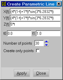
The required input data are the mathematical formulas of the coordinates X(t), Y(t), Z(t),
where 't' is the parameter of the curve, and its value belongs to the interval [ t0-t1 ]
The curve is created by approximation. That curve is a NURBS (Non Uniform Rational B-Spline) which is created with N points. In GiD these kinds of curves are cubical (degree 3).
EXAMPLE
We fill the formulas with the expression of a conic helix. That helix starts with radius R0=4 and finishes with radius R1=1, performing N=3 turns from t=0.0 to t=1.0, the height also changes from 0 to H=5.
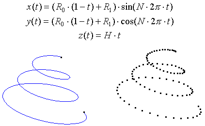
Example of conic helix with a unique curve or with only points
Polyline creation |
![]()
![]()
Polylines are a set of other lines (two, at least) of any type (including polylines themselves). Every line must share one or two of its endpoints with the endpoints of other lines.
There are two possible ways to create a polyline, either by selecting one line and searching the rest until a corner or end is reached or by selecting several lines (see section Entities selection). In the case of the latter, the order of selection is not important but all of them must join each other by sharing common points.
Polylines are drawn in green to show the difference between the other lines, which are drawn in blue.
Polylines are widely used when creating 4-sided surfaces (see section 4-sided surface creation) and automatic 4-sided surfaces (see section 4-sided surface automatic creation).
When deleting a polyline, all its lines are also deleted. When exploding (see section Polyline), the polyline will disappear and its individual lines will appear.
It is not possible to create third level polylines: one former polyline can be included inside another, but not the new one.
Option Number Lets the user choose the label that will be
assigned to the next created line. If a line with this number already
exists, the old line changes its number.
Arc creation |
![]()
![]()
To create an arc it is necessary to enter 3 points (By 3 points) (see section Point definition) or
enter a radius and the two tangent lines at the arc ends (Fillet curves).
It is important to note that when creating an arc, new points are also being created (if not using existing ones).
An arc that begins and ends on one of the first or third points defined is always created. The arc will always contain the second point. This one is only used as a reference and, if non-existent, it is automatically erased when the arc is created.
Option Undo undoes the creation of the last point (if new). It is possible
to continue undoing back until the first point.
Option Fillet curves lets the user input a radius and select two lines
that share one common point. An arc will be then created and the two lines will
be modified to be tangent and continuous with this new arc.
To convert one arc to another one with the same center and in the same plane
but with complementary angle, command Swap arc can be used
(see section Swap arc).
NURBS surface creation |
![]()
![]()
NURBS are non-uniform rational B-splines. They are a type of surfaces defined by their control polygon (one set of points that the surface approximates smoothly); one set of knots for the two senses u and v (a non-decreasing list of real numbers between 0 and 1) and, optionally, one set of rational weights.
To draw the isoparametric lines in u,v=0.5, check Surface drawing type
(see section Preferences).
-
By contour:creates a NURBS by their contour lines. GiD calculates automatically the interior information of the surface so as to interpolate the boundaries smoothly.
To create a NURBS surface, some lines must be selected (see section Entities selection). The order of selection is not important but all of them must join each other by sharing common points and must form a closed contour. Number of lines must be equal or bigger than one and shape must be topologically similar to a triangle or a quadrilateral in the space, for the algorithm to work correctly. This last argument is not necessary if all the lines lie in one plane. In this case, the surface is created as a trimmed one and problems about the shape are avoided. It is possible to select the boundary lines and the boundary lines of interior holes at the same time, if all the lines belong to a plane.
Note: OptionNo try planar(this option is found in the Contextual mouse menu) avoid the creation of a trimmed NURBS surface when lines are coplanar.
Note: To enter rational weights to the surface, use commandEdit NURBS surface(see section Edit NURBS line/surface).
-
Automatic:creates automatically all possible surfaces with a number of sides given by the user. Every new surface will be created in the current layer.
Caution: When creating some surfaces at the same time, it is possible that some undesired surfaces may also be created. It is necessary to check the surfaces after creation and erase the undesired ones.
-
Trimmed:this option let the user select one existing NURBS surface and a set of closed lines that are inside the surface. Some of these lines may belong already to the contour of the existing surface. Some other lines may be created with an intersection with another surface. Another new surface will be created without changing the old one. It is possible to select the boundary lines and the boundary lines of interior holes at the same time, if all the lines belong to the surface:

-
UntrimmedConstructs one new surface with the selected surface as base and as contours, the natural contours of the NURBS surface. The resulting surface is not trimmed.
-
Parallel lines:permit to create one surface given a set of parallel lines in the space. The new surface will interpolate all the selected lines.
-
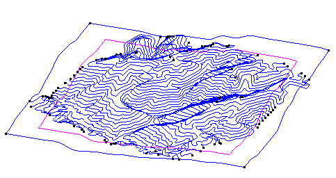
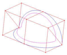
By points/By line points:these two options are available in the Contextual mouse menu after the NURBS surface creation tool is selected.By pointscreates a NURBS surface from a cloud of points, andBy line pointscreates a NURBS surface from level curves. This two functions are very useful to create relieves and terrains. In the image below, a NURBS surface created from level curves:
-
Search:lets the user select one line and creates one surface that contains this line.
Parametric surface |
![]()
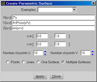
The required input data are the mathematical formulas of the coordinates X(u,v), Y(u,v), Z(u,v), where 'u' and 'v' are the parameters of the surface, and its value belongs to the intervals set in 'u in' and 'v in' respectively. The surface is created by approximation. That surface is a NURBS (Non Uniform Rational B-Spline) which is created with 'Number of points U' x 'Number of points V' points. In GiD these kinds of surfaces are cubical (degree 3).
Planar surface creation |
Note: Entity planar surface has been substituted by entity NURBS surface (see section NURBS surface creation). This entity automatically detects if boundary lines lie in a plane and create a planar NURBS.
Note: It is possible to access to this deprecated function with the Right buttons (see section Tools).
Planar surface is an entity formed by a closed set of lines, all of them lying on the same plane. Lines must share endpoints between them.
To create a planar surface, some lines must be selected (see section Entities selection). The order of selection is not important but all of them must join each other by sharing common points and must form a closed contour. If all lines are not in the same plane the surface is not created.
It is possible to add holes to a planar surface. To do so, it is first necessary to
create the outside planar surface. After this, press Hole button and select
the created surface. Then, select lines that form every hole, one by one. Finish
with escape (see section Escape).
It is also possible to define the surface and holes at the same time, selecting all the curves.
If the surfaces lie on the plane z=0, the orientation of the surfaces will be
anti-clockwise in this plane (the normal vector points towards z positive).
Otherwise,
orientation will be arbitrary. This can be checked with the DrawNormals command
(see section Normals).
4-sided surface creation |
Note: Entity 4-sided surface has been substituted by entity NURBS surface (see section NURBS surface creation). This new entity has all the functionality of the old one.
Note: It is possible to access to this deprecated function with the Right buttons (see section Tools).
A 4-sided surface is an entity formed by a closed set of four lines in the space. Its mathematical definition is a bilinear Coon's surface. The surface is totally defined by the shape of the lines, with no information about the interior. This means that, sometimes, it will be necessary to use more surfaces to obtain a good shape definition.
To create a 4-sided surface defined by three lines, it is necessary to divide one of the lines in two pieces (see section Divide). Then, the creation of a 4-sided surface is possible.
To create a 4-sided surface, several lines must be selected (see section Entities selection). The order of selection is not important, but all of them must join each other by sharing common points and they must form a closed contour. If the creation is not possible, information about the endpoints is displayed in one window.
In order to make one or more lines form parts of a polyline (see section Polyline creation), select the entire polyline as one of the lines and GiD will automatically select the piece or pieces of the polyline that are required. Using this facility, non-conforming surfaces can be created. This means creating a surface by using the entire line on one side of the polyline, and creating more than one 4-sided surface by using parts of it on the other side.
When selecting more than four lines, GiD will automatically search for all the possible 4-sided surfaces that can be created with these lines. This allows the creation of many surfaces at the same time.
The button Automatic is equivalent to 4-sided surface automatic creation
(see section 4-sided surface automatic creation).
If the surfaces lie on the z=0 plane, the orientation of the surfaces will be
anti-clockwise in this plane (normal vector points towards z positive).
Otherwise, the
orientation will be arbitrary. This can be checked with the DrawNormals command
(see section Normals).
Option Number Lets the user choose the label that will be
assigned to the next created surface. If a surface with this number already
exists, the old surface changes its number.
Caution: When creating some surfaces at the same time, it is possible that some undesired surfaces may also be created. It is necessary to check the surfaces after creation and erase the undesired ones.
4-sided surface automatic creation |
Note: Entity 4-sided surface has been substituted by entity NURBS surface (see section NURBS surface creation). This new entity has all the functionality of the old one.
Note: It is possible to access to this deprecated function with the Right buttons (see section Tools).
Inside this option, GiD creates as many 4-sided surfaces as it can find. Every new surface will be created either in the current layer.
Caution: When creating some surfaces at the same time, it is possible that some undesired surfaces may also be created. It is necessary to check the surfaces after creation and erase the undesired ones.
Contact surface creation |
![]()
Contact surfaces defined between two lines that are physically in the same place but with different entities as lines and points. From a contact surface, it is possible to generate contact elements or algorithms that define special contact between two bodies.
Those lines that have been generated from another one, although not physically in contact, or simply, identical surfaces separated by a movement, can obtain equal meshes from this option, ensuring a one-to-one relationship between nodes.
It is necessary to choose contact surface to create
contact surfaces.
After this, it is necessary to choose lines.
Contact elements are, by default, 4-node planar quadrilaterals.
However, the user can select 2-node lines for all cases (see section Element type).
The 4-node planar quadrilaterals can be converted to the 8-node or 9-node for the quadratic case.
The user can also select no mesh for the contact entity. This makes it possible to have
exactly the same mesh in both lines but without any additional element.
Surface mesh |
![]()
With this option a Surface mesh can be created by selecting triangle or quadrilateral
mesh elements (see section Surface mesh).
Volume creation |
![]()
![]()
A volume is an entity formed by a closed set of surfaces that share their lines between them.
To create a volume, some surfaces must be selected (see section Entities selection) using the
option By contour.
The order of selection is not important but all of them must join each other by
sharing common lines and they must form a closed contour.
If there is an error and the volume is not created, helpful information is displayed in one window.
Option Search lets the user select one surface and create one of
the volumes that contains this surface.
It is possible to add holes to a volume. To do so, it is first necessary
to create the outside and the interior volumes as independent
volumes. After this, push Hole button and select the outside
volume. Then, select the interior volumes that form every hole, one by
one. Finish with escape (see section Escape).
Orientation of volumes and their surfaces is automatically set to facilitate a correct meshing.
An additional feature allows the selection of surfaces that form the outer part of the volume as well as the ones that form the holes at the same time. In this case, GiD automatically recognizes the holes.
Option Automatic 6-sided volumes creates all possible volumes that have 6 sides (contour surfaces).
It can be applied several times over the geometry and volumes are not repeated.
Every new volume will be created in the current layer.
It can be useful for structured meshing (see section Structured).
Contact volume creation |
![]()
Contact volumes are defined between two surfaces that are physically in the same place but with different entities as surfaces, lines and points. From a contact volume, it is possible to generate contact elements or algorithms that define special contact between two bodies.
Those surfaces that have been generated from another one, although not physically in contact, or simply, identical surfaces separated by a movement, can obtain equal meshes from this option, ensuring a one-to-one relationship between nodes.
It is necessary to choose contact volume to create
contact volumes. After this, it is necessary to choose surfaces.
GiD automatically searches possible contacts combining selected surfaces in pairs.
Contact elements are, by default, 8-node hexahedra or 6-node prisms (depending on the surface mesh). However, the user can select 2-node lines for all cases (see section Element type).
The result elements can be also quadratic.
The user can also select no mesh for the contact entity. This makes it possible to have
exactly the same mesh in both surfaces but without any additional element.
When creating contact volumes, GiD internally checks what surfaces occupy the same location in the space and creates the contact, therefore there is no need to specify what surfaces have to be in contact. For this reason, several surfaces can be selected at once and GiD performs the contact automatically, indicating the number of contact volumes that have been generated.
A feature in GiD is the option of creating contact separated volumes for
surfaces that are not physically in contact.
For these separated volumes, GiD internally checks whether there exists a unique solid-rigid movement between two surfaces and creates the contact between both. There is the possibility of the existence of more than one solid-rigid movement between two of them. In this situation, GiD asks for the point image of a particular original point to define the movement and, consequently, applies the right contact.
Object |
![]()
![]()
With this command it is possible to create several objects which are:
- Rectangle
- Polygon
- Circle
- Sphere
- Cylinder
- Cone
- Prism
- Torus
When creating an object, GiD asks for a center and a normal. To enter the coordinates of the center you can click on the screen or select an existing point (see section Point definition). To enter the normal, GiD displays a window where you can choose one of the three axes or enter the coordinates of a point.
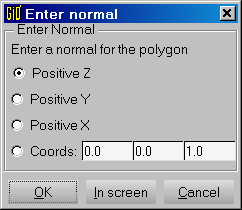
The button In screen of the Enter normal window, lets you manually enter the coordinates of the point which defines the normal: you can directly click on the screen or pick an existing point using the option Join C-a of the Contextual mouse menu.
When using the commands sphere, cylinder, cone,
prism or torus the volume of the object is also created.
Delete |
![]()
![]()
The deletion of entities can be done in two ways: at one level (point,
line, surface or volume) or erasing all entities at once. A
selection is made (see section Entities selection) in both cases. After pressing
escape (see section Escape), the entities are erased.
To avoid erasing the selected entities, press Clear selection in the Contextual menu.
Entities which depend on higher entities, cannot be erased. For example, if a surface is created over some lines, it is necessary to erase the surface before erasing the lines.
Edit |
These are GiD editing options for geometrical entities:
- Move point
- Divide lines, polylines or surfaces
- Join lines end points
- Force lines to be tangent
- Swap arc
- Ecplode or edit polylines
- Edit SurfMesh
- Edit NURBS lines or surfaces
- Convert to NURBS lines or surfaces
- Simplify NURBS lines or surfaces
- Hole NURBS surface
- Collapse or Uncollapse entities or model
- Intersections between entities
- Surface or volume boolean operations
Move point |
![]()
By using this command, an existing point is selected and moved. The new position is
entered in the usual way (see section Point definition). If the new position is an
existing point (when using join), GiD will determine the distance between the
points and ask if they should be joined. If answered yes, both points are
converted into one. Lines and surfaces joined to the point are also moved and
deformed to maintain their links.
Divide |
![]()
Command Divide, can be applied either to lines, polylines or surfaces (trimmed surfaces included).
In case of polylines, the user must choose an existing interior point. The polyline
will be converted into two lines that may or not be polylines.
Polyline division have an option Angle that permits to divide the polyline
in all the points where the angle between the sub lines before and after is bigger
than the given one.
Caution: An interior point must belong to level one of a polyline
(see section Polyline creation).
In case of lines and surfaces, after selecting the entity,
the division can be given in several ways:
- Number of divisions: line or surface will be converted in equally spaced pieces.
- Near point: With this option one point must be selected near the line or the surface. Points inside the entities can be selected. See section Option point in line, or See section Option point in surface. The line or the surface will be divided into two entities near that point.
- Parameter: One factor is given between 0.0 and 1.0 and entity will be
divided where the parametric variable takes that value.
- Lines
- Relative length: One factor is given between 0.0 and 1.0 to divide
the line with relative arc length ratio equal to the selected factor. (Same concept as
Parameterif the curve was arc length parameterized).
- Length: Length of the result divided lines is given, and GiD divides the line in as many lines as it can. If length given is bigger than selected line length no division is made.
- Relative length: One factor is given between 0.0 and 1.0 to divide
the line with relative arc length ratio equal to the selected factor. (Same concept as
- Surfaces
- Split: surface will be divided following the divide lines. These lines must intersect the surface contour.
(command:
Geometry Edit SplitSurf)

uorv. This sense can be previously checked with the command Edit NURBS Surface. (see section Edit NURBS line/surface) - Split: surface will be divided following the divide lines. These lines must intersect the surface contour.
(command:
Note: After the division, the entity disappears and new entities are created.
Lines operations |
![]()
This option allows the user to edit groups of lines in respect with their topology and shape.
Join lines end points:
With command Join lines end points, two lines must be selected. GiD determines the
distance between the two closest endpoints, draws both points and asks
for confirmation. If one of the lines is a polyline, interior points are
also considered. If accepted, the points are converted into one and the lines are
deformed. The new point will then take the place of the first line's point.
See section Move point, for another method of converting two points into one.
Caution: Second selected line cannot have higher entities (second point is moved to first).
Force to be tangent:
With command Force to be tangent, two lines (witch share at least one point) must be selected.
They must be NURBS lines, otherwise they will be rejected. User is asked to enter the maximum angle
between lines to accept the operation, and GiD modify NURBS lines selected
to force them to be tangent in their common point.
Swap arc |
![]()
This command lets the user select and alter arcs. Lines that are not arcs are rejected. After confirmation, the arc is converted to a new arc with the same center and in the same plane but opposite the old one. The old arc disappears and the angle of the new arc will be supplementary to the angle of the old arc.
Caution: Arcs with higher entities cannot be swapped.
Polyline |
![]()
Explode polyline:
This command lets the user select lines. Lines that are not polylines or have higher entities or conditions are rejected. After confirmation, the polylines are exploded and converted into their original lines. Polylines then disappear (see section Polyline creation).
Edit polyline:
The command Edit Polyline allows the user select lines. Lines that are not
polylines are rejected. It is possible to choose several options for the polylines:
- Use points: When meshing this polyline, there will be at least one node at every point location that defines the polyline. These will be the endpoints of interior lines.
- Not use points: When meshing this polyline, the mesh generator ignores the points and therefore, the nodes will be placed anywhere. This is the default option. Nodes will only be put in the position of a point if there is a 4-sided surface over a part of a polyline (see section 4-sided surface automatic creation).
- Only points: When meshing this polyline, the nodes will only be placed where the geometry points are.
Note: If one condition is assigned to one interior point of a
polyline (see section Conditions), one node of the mesh will be placed over
that point.
SurfMesh |
![]()
User must select one or several surface meshes (see section Surface mesh). Options are:
- Draw mesh: Surface will be drawn as a mesh.
- No draw mesh: Surface will be drawn as a regular surface. With magenta lines close to the boundary lines.
Edit NURBS line/surface |
![]()
Edit NURBS line:
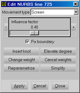
Once a NURBS line is selected (use the Pick button of the Edit NURBS Line window), it is possible to interactively edit
its control points (see section NURBS line creation). Select the control points
as if they were regular points and enter their new positions in the usual way
(see section Point definition).
The Influence factor affects the movement propagation of the neighbouring control points.
Options:
- Fix boundary
Check option
fix boundary, if you don't want to move the boundary control points of the line. - Insert knot: User is asked for a knot value between 0.0 and 1.0 and this is inserted. Program checks that knot multiplicity is not bigger than order (order=degree+1). As the number of knots increase, the number of control points also increases, so this option can be used to have more points defining the same curve.
- Elevate degree: With this option degree of the curve is elevated by one. The new curve will have the same shape but with more control points and knots.
- Change Weight: A new positive weight can be introduced for any control point, except the end points.
- Cancel weights: All weights of the NURBS are converted to 1.0 and the curve is no more rational.
- Reparametrize: With the same control points a new curve is calculated to get a better curve with a more uniform parametrization.
- Simplify: This option converts the curve to a simplified curve, which is an approximation of the original one.
Edit NURBS surface:
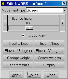
Once a NURBS surface is selected (use the Pick button of the Edit NURBS Surface window), it is possible to interactively edit
its control points (see section NURBS surface creation). Select the control points
as if they were regular points and enter their new positions in the usual way
(see section Point definition).
Options:
- Insert knot: User is asked by a knot value between 0.0 and 1.0 and it is inserted. Program checks that knot multiplicity is not bigger than order. This option can be used to have more points defining the same surface.
- Elevate degree: With this option degree of the surface is elevated by one. The new surface will have the same shape but with more control points and knots.
- Change Weight: A new positive weight can be introduced for any control point, except the extremes.
- Cancel weights: Converts the weights of all the control points to 1.0
- Simplify: Simplifies the surface (if possible) removing the less significant knots.
- Reparametrize: Reparametrizes the surface obtaining an optimized surface. When a Nurbs surface is not well parametrized, the mesh has a worse quality.
The Movement type menu of the Edit NURBS Surface window, determines the kind of movement of the selected knots. This movement can be along an axis (X-Axis, Y-Axis, Z-Axis), describing the Normal of the surface (Normal), following the screen movement of the mouse (Screen) or the new location of the knot can be defined introducing the coordinates of a point (Point).
Note: Options Insert knot and Degree elevate can be chosen
for the u or the v parameters direction.
Convert to NURBS line/surface |
![]()
This option converts the selected lines or surfaces to NURBS lines or NURBS surfaces.
Note: Some algorithms only work with NURBS entities.
Simplify NURBS line/surface |
![]()
This option converts the selected NURBS lines or surfaces to other ones very similar to the originals but with and easier definition. It can be useful for imported data that is defined with a too complex control polygon and displays or is meshed too slow.
Hole NURBS surface |
![]()
This option let the user select one existing NURBS surface and a set of closed lines that are inside the surface and that form a hole inside it. The lines may be created with an intersection with another surface. The hole will be added to the existing surface.
Collapse |
![]()
The function Collapse converts coincident entities or entities that are
close each other enough into one.
The variable ImportTolerance (see section Preferences), controls the maximum
distance between two adjacent points to be converted into one. With lines
and surfaces, a maximum distance between both entities is calculated and
when it is less than ImportTolerance, they are converted into one.
Select the type of entities: point, line, surface
or volume, when being in geometry mode. All the lower entities that
belong to the selected ones will be automatically computed. After pressing
escape, collapse is performed.
Option Model performs the operation over all the gemoetrical entities of the model.
Uncollapse |
![]()
Function uncollapse permits the user to select lines, surfaces or volumes and duplicate all common lower entities.
Typically, if two surfaces share one line as an edge, after applying this function to both surfaces, that line and his shared points will be duplicated and every line will belong to a different surface.
This feature is interesting for example to un-connect joined bodies, or to generate a non-conformal mesh with less elements that a conformal one.
Intersection |
![]()
Using this option, many geometrical entities intersenctions can be performed.
Intersection line-line |
With command Intersect lines, two lines must be selected. GiD
searches the closest points between the two lines. If the lines do not
intersect, GiD determines the distance between the two closest points,
draws both points and asks for confirmation. Otherwise, the new point
will be the intersection point. If confirmed, the two lines are
converted into four and the second point is moved to the one in the
first line and converted into a unique point (if interior points of one
or two of the lines coincide with endpoints, only two or three new lines
are created). Polylines cannot accept this option.
Option No divide lines creates the intersection point but do not modify
the lines.
Note: This option can be used to extend one line until reaching the other
line.
Caution: Second selected line can have higher entities only if it is not necessary the extension of this line.
Intersection multiple lines |
This option lets the user select several lines. Then, it tries to find as many intersection points between them as possible. Lines are divided when applicable.
Option No divide lines creates the intersection point but do not modify
the lines.
Intersection Surface 2 points |
User must select one surface and two points that lie approximately over the surface. GiD calculates the line intersection between the surface and a plane defined by the two given points and the average normal to the surface in these points.
Note: Planar surfaces cannot be used with this option.
Note: See section Option point in line, or See section Option point in surface, can be used
to define the points.
Intersection Surface lines |
User must select one NURBS surface and several lines. GiD calculates the intersection between the surface and the lines. Lines will be divided in the intersection point.
Option No divide lines creates the intersection point but do not modify
the lines.
Option Extend Divide lines and also extends lines until they reach the
surface.
Intersection Surface surface |
This command creates the intersection lines between two surfaces. If these lines intersect surfaces contour lines, these are divided.
Option No divide lines creates the intersection point but do not modify
the contour lines.
Option No divide surface. By default the surfaces are divided, unless this option is selected.
Intersection Multiple surfaces |
This command creates the intersection lines between surfaces.
Surface boolean operations |
![]()
User must select the two 2D surfaces located in the XY plane (order is important in subtraction).
The valid surface boolean operations are:
Union: fuses two surfaces wherever they intersect to create a single, more complex volume.Intersection: creates a surface based on the intersecting points of two separate volumes.Subtraction: negates a specific portion of a surface to create a hole or indentation.
Volume boolean operations |
![]()
The GiD Volume Boolean Modeler has been designed to accomplish geometric feats as physically punching a hole trough a volume, combining two volumes into one and creating a new volume from the intersecting points of two separate volumes.
The valid volume boolean operations are:
Union: fuses two volumes wherever they intersect to create a single, more complex volume.Intersection: creates a volume based on the intersecting points of two separate volumes.Subtraction: negates a specific portion of a volume to create a hole or indentation.
User must select the two volumes (order is important in subtraction).
Go to the first, previous, next, last section, table of contents.