FILES |
Browser to read and write files and projects.
GiD includes the usual ways of saving and reading
saved information (Save, Read) and other file capabilities, such as
importing external files, saving in other formats and so on.
New |
![]()
![]()
New opens a new project with no title assigned.
If this option is chosen from inside a project where some changes have been introduced, GiD asks to save them before entering the new project. Next, a new problem without a title begins.
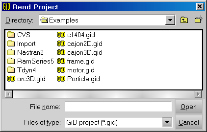
Open |
![]()
![]()
With this command, a project previously saved with Save (see section Save) or with
Save ASCII project (see section ASCII project) can be open.
Generally, there is no difference between using a project name with the .gid
extension or without it.
Save |
![]()
![]()
Save a project is the way of saving all the information relative to the
project: geometry, conditions, materials, mesh, etc. onto the disk.
To save a project, GiD creates a directory with its name and extension .gid.
Some files are written into this directory containing all the information. Some of
these files are binary and others are ASCII. The user can then
work with this project directory as if it were a file.
User doesn't need to write the .gid extension because it will be automatically
added to the directory name.
Caution: Be careful if changing some files manually into the Project.gid directory. If done in this way, some information may be corrupted.
Advice: It is advisable to save often to prevent losing information. It is possible to automatically save a model backup by selecting a user frequency (see section Preferences).
Save as |
![]()
With this command, GiD allows the user to save the current project with another name.
When it is selected, an auxiliary window appears with all the existing projects and directories to facilitate the introduction of the project's new name and directory.
Import |
GiD allows to import geometrical models or meshes in several formats, as the ones presented afterwards.
IGES |
![]()
With this option it is possible to read a file in IGES format, version 5.3.
GiD can read files in IGES version 5.3 format, including most of the entities, which are:
Entity number and type (Notes)
100	Circular arc
102	Composite curve
104	Conic arc (ellipse, hyperbola and parabola)
106	Copious data (forms 1, 2, 12 and 63)
108	Plane (form1 bounded)
110	Line
112	Parametric spline curve
114     Parametric spline surface
116     Point
118     Ruled surface
120     Surface of revolution
122     Tabulated cylinder
124     Transformation matrix (form 0)
126	Rational B-spline curve
128	Rational B-spline surface
140     Offset surface entity
141     Bounded entity
142     Curve on a parametric surface
143     Bounded surface
144     Trimmed surface
186     Manifold solid B-rep object
308     Subfigure definition
402     Associativity instance
408     Singular subfigure instance
502     Vertex
504     Edge
508     Loop
510     Face
514     Shell
The variable ImportTolerance (see section Preferences) controls the creation of
new points when an IGES file is read.
Points are therefore defined as unique if they lie further away than this tolerance
distance from another already defined point. Curves are also considered identical if
they have the same points at their extremes and the "mean proportional distance"
between them is smaller than the tolerance. Surfaces can also be collapsed.
Entities that are read in and transformed are not necessarily identical to the original entity. For example, surfaces may be transformed into plane, into Coons or into NURBS surfaces defining their contours and shape.
DXF |
![]()
With this option it is possible to read a file in DXF format, version AutoCAD 2002.
Mostly all the geometry in the DXF is read except the solid modelled entities.
A very important parameter to consider is related to how the points must be joined.
This means that points that are close to each other must be converted to a single
point.
This is done by defining variable ImportTolerance (see section Preferences).
Points closer together than ImportTolerance will be
considered to be a single point. Straight lines that share both points are also
converted to a single line.
User can perform one Collapse (see section Collapse) to join more entities.
Parasolid |
![]()
With this option it is possible to read a file in Parasolid format.
GiD can read files in Parasolid version 14000 format (ASCII or binary formats).
The most usual Parasolid file extension is .x_t for ASCII and .x_b for binary format.
The variable ImportTolerance (see section Preferences) controls the creation of
new points when a Parasolid file is read.
Points are therefore defined as unique if they lie further away than this tolerance
distance from another already defined point. Curves are also considered identical if
they have the same points at their extremes and the "mean proportional distance"
between them is smaller than the tolerance. Surfaces can also be collapsed.
ACIS |
![]()
With this option it is possible to read a file in ACIS format, version 7.0.
GiD reads the ASCII version, the SAT Save File Format. ACIS files (in ASCII) have the .sat extension.
VDA |
![]()
With this option it is possible to read a file in VDA 2.0 format.
A very important parameter to consider is related to how the points must be joined.
This means that points that are close to each other must be converted to a single
point.
This is done by defining variable ImportTolerance (see section Preferences.
Points closer together than ImportTolerance will be
considered to be a single point. Straight lines that share both points are also
converted to a single line.
User can perform one Collapse (see section Collapse) to join more entities.
Rhino |
![]()
With this option it is possible to read Rhino 3.0 CAD files.
Shapefile |
![]()
With this option it is possible to read a GIS file written in ESRI Shapefile format, version 1000.
Shapefiles have the .shp extension.
NASTRAN mesh |
![]()
With this option it is possible to read a file in the NASTRAN format, version 68.
GiD can read files written in NASTRAN version 68 format, accepting most of its entities, which are:
Entity name ( Notes)
CBAR CBEAM CROD CCABLE CBUSH CELAS1 CELAS2 CELAS3 RBAR (translated as 2 node bars)
CQUAD4 CQUADR
CHEXA
CTETRA
CPENTA
CTRIA3 CTRIAR
CONM1 CONM2 (translated as 1 node element)
CORD1C CORD1R CORD1S
CORD2C CORD2R CORD2S
GRID
There are two options that can be used when reading a mesh if GiD already contains a mesh:
-
a) Erasing the old mesh (
Erase) -
b) Adding the new mesh to the old without sharing the nodes; the nodes will be
duplicated although they will occupy the same position in the space
(
AddNotShare).
The properties and materials of elements are currently ignored, because of the difficulties in associating the NASTRAN file properties with the requirements of the analysis programs. The user must therefore assign the materials "a posteriori" accordingly. However, in order to make this easier, the elements will be partitioned into different layers each with the name PIdn, where n is the property identity number associated with the elements as defined in the NASTRAN file. Note that CELAS2 elements do not have associated property identities so these will be created by default during the reading of the file.
STL mesh |
![]()
With this option it is possible to read a mesh in STL format. The STL binary format is also supported.
The variable ImportTolerance (see section Preferences) controls the creation of
new points when the file is read.
VRML mesh |
![]()
With this option it is possible to read a mesh in VRML 2.0 format.
The compressed gzip format is also supported.
3DStudio mesh |
![]()
With this option it is possible to read a mesh in .3ds 3DStudio format.
GiD mesh |
![]()
With this option it is possible to read a GiD ASCII mesh (saved with Export GiD Mesh) in order to visualize it within GiD.
It is also possible to read a new mesh and add it to the existing one. In this case, the user is prompted to keep the former one or join it to the new mesh.
The format of the file (whose name is introduced by means of the command line or directly by getting it from the auxiliary window) describing the mesh must have the following structure:
mesh dimension = 3 elemtype tetrahedra nnode = 4
coordinates
1 0 0 0
2 3 0 0
3 6 0 0
4 3 3 0
5 3 1.5 4
6 3 1.5 -4
7 1.5 0 2
end coordinates
elements
1 1 2 4 5 1
2 2 3 4 5 1
3 1 4 2 6 1
4 2 4 3 6 1
5 1 2 5 7 1
end elements
Code nnode means the number of nodes per element and
dimension can be either:
2: 2 dimensions. Nodes have just two coordinates.3: 3 dimensions. Nodes have three coordinates.
Where elemtype must be:
- Linear
- Triangle
- Quadrilateral
- Tetrahedra
- Hexahedra
Every element may have an optional number after the connectivity's
definition. This number usually defines the material type and it is
useful to divide the mesh into layers to visualize it better. GiD offers
the possibility of dividing the problem into different layers according
to the different materials through the option Material
(see section Layers).
Note: The sign = is optional, but if it is present it is
necessary to leave a space.
If it is necessary to enter different types of elements, every type must
belong to a different mesh. More than one mesh can be entered by writing
one after the other, all of them in the same file. The only difference
is that all meshes except the first one have nothing between
coordinates and end coordinates. They share the first
mesh's points. Example: to enter tetrahedra elements and triangle
elements,
mesh dimension = 3 elemtype tetrahedra nnode = 4
coordinates
1 0 0 0
2 3 0 0
3 6 0 0
4 3 3 0
5 3 1.5 4
6 3 1.5 -4
7 1.5 0 2
end coordinates
elements
1 1 2 4 5 1
2 2 3 4 5 1
3 1 4 2 6 1
4 2 4 3 6 1
5 1 2 5 7 1
end elements
mesh dimension = 3 elemtype triangle nnode = 3
coordinates
end coordinates
elements
1 1 2 4 1
2 2 3 4 1
3 1 4 2 1
4 2 4 3 1
5 1 2 5 1
end elements
Surface mesh |
![]()
With this option, a mesh can be read from a file in GiD or STL format (see section GiD mesh). Elements of this mesh must be triangles or quadrilaterals. This mesh is converted by GiD in a set of surfaces, points and lines. The geometric definition of surfaces is the mesh itself, but GiD treat them as truly geometric entities. For example: these surfaces can be used as the boundary of a volume, and a new mesh can be generated over them.
User is asked for the value of an angle. An angle between elements bigger than this value is considered to be an edge, and lines are inserted over them. As a consequence, a set of boundary and interior lines are created and attached to the surfaces to mark their edges.
Batch file |
![]()
Sometimes, it may be useful not to use GiD interactively. To do so, commands can be written into a file and GiD will read this file and execute the commands. These commands are the same that are used in GiD when written in the command line or using the commands in the right side commands menu.
Example: Many points have been digitalized and their coordinates saved in a file. These points are to be joined with straight lines to create the outline of the geometry. To do so, the file would look similar to this:
geometry create line
3.7 4.5 8
2 5 9
4,5,6
 ...
1 7 0.0
escape
A batch file can also be loaded into GiD by giving its name with option -b
when opening GiD. (see section INVOKING GiD) Another way to read batch files to create dynamic presentations is with the Read batch window (see section Read batch window). One GiD session can be registered in a batch file. This can be useful to check the batch commands or to repeat one session (see section Preferences).
BATCH FILE COMMANDS
There are some especial commands to be added to a batch than are treated differently than regular GiD commands. Their format is one or several words after the control string ***** (five stars) and everything in one line.
- Write a log file
*****OUTPUTFILENAME filename
filenameis substituted with a real file name where all the session warnings (that which appear in the GiD messages warn line) are written. This can be useful when running GiD in batch with option -n (see section INVOKING GiD) and GiD output is desired.
- Execute a Tcl command in a batch file
*****TCL tcl_command
Note: If this command is used in batch file and GiD is invoked with option-nit will not work. To make Tcl commands execute when GiD is executed without any window, you should use the-n2option. (see section INVOKING GiD)
- Insert comments in the code of a batch file
geometry create line
1,2
*****COMMENTS -this is a comment-
2,3
escape
- Print messages in the inferior GiD messages line
geometry create line
1,2
*****PRINT  -This is a message which will appear in the messages line-
2,3
escape
- Print messages in a window
geometry create line
1,2
*****PRINT1  -This is a message which will appear in a new window-
2,3
escape
Insert GiD geometry |
![]()
This command permits to insert one previously created GiD model inside another one. Entities from the old and the new model are not collapsed.
User can perform one Collapse (see section Collapse) to join the old and new model.
Export |
GiD allows to export geometrical models or meshes in several formats, as the ones presented afterwards.
IGES |
![]()
GiD can export the geometry in IGES format (version 5.3).
If the preference 'IGES:B-Rep output style' is set (see section Preferences), then the output file is written in Boundary representation solid model style, else the surfaces are written as separated trimmed surfaces, without topological information, and the volumes are ignored.
The IGES geometric entities generated are:
116	Point
110	Line
102	Composite curve
126	Rational B-spline curve
128	Rational B-spline surface
142	Curve on a parametric surface
144	Trimmed surface
and the topological entities are (B Rep style):
186     Manifold solid B-rep object
502     Vertex
504     Edge
508     Loop
510     Face
514     Shell
DXF |
![]()
GiD can export the geometry in DXF format (version AutoCAD 2002). Points and curves are correctly exported, but surfaces shape can be changed by a mesh of triangles, because DXF does not support Trimmed NURBS Surfaces.
ACIS |
![]()
GiD can export the geometry in ACIS ASCII format, version 5.0 (files with .sat extension).
GiD mesh |
![]()
With this option a file is written with all the project's mesh or meshes inside.
This file can be read with Import GiD Mesh See section GiD mesh.
Text data report |
![]()
With this option a file is written containing all the information within the project. It is created in a way that is easily understood when read with an editor. This is useful for checking the information.
Note: This ASCII format is only used to check information. It cannot
be read again by GiD. To write ASCII files that can be read again use the option
SaveAsciiProj (see section ASCII project).
ASCII project |
![]()
This option saves a project in the same way as the regular save
(see section Save) but files are written in ASCII. It may be useful to copy
projects between non-compatible machines. GiD also allows this
information to be written in a file (see section Text data report).
Projects saved in this way may be read with the same open command
(see section Open).
ON layers |
![]()
With this option, only the geometrical entities with its
layer set to ON will be saved
in a new project (see section Layers).
Note: Lower entities necessary to define the saved entities will be also saved into the new project (example: The two points extremes of a line are also saved if the line is saved).
Calculation file |
![]()
If GiD runs the solver module automatically, this command is not necessary. It is however useful if the solver program is required to be run outside GiD, or to check the data input prior to any calculations.
This command writes the data file needed by the solver module.
The format of this file must be defined in a Template File (see section Template File). GiD uses the template file of the current Problem Type to write the data file; so, to run this command, a problem type must be selected.
When testing a new problem type definition, GiD produces messages about errors within the configuration. When the error is corrected, the command can be used again without quitting the example and without having to reassign any condition or meshing again.
Using template .bas |
![]()
This command does the same as Export calculation file (see section Calculation file), but it uses a .bas file provided by the user, instead of using the template file of the current Problem Type. So, it's not necessary to select a Problem Type to run this command.
When choosing option Others... from the submenu, GiD asks for a .bas file (see section Template File) and, using that file, writes the data file needed by the solver module. There are some .bas codes available in the submenu which write output files in some formats (DXF, NASTRAN, STL, VRML). These example .bas files are located in the Templates directory of the main GiD directory. It's possible to add other .bas files to that directory so that they appear in the submenu.
Preprocess/Postprocess |
![]()
![]()
![]()
This command allows to go to Postprocess part when user is in Preprocess part and vice versa.
Print to file |
![]()
![]()
This option asks the user for a file name and save an image in the
required format. The properties of the image (resolution, size, etc.) can
be assigned in Page/image setup (see section Page/image setup).
Accepted formats are:
Postscript screen:Postscript. Useful to send to a postscript printer. It is a snapshot of the screen.Postscript vectorial:Postscript. Useful to send to a postscript printer. It gives higher quality but it is only usable for small models. Otherwise, very large files are created and it takes very long time to print them.EPS screen:Encapsulated postscript. Useful to insert in documents.EPS vectorial:Encapsulated postscript. Useful to insert in documents. It gives higher quality than EPS screen, but the resulting file is much bigger.BMP:Windows Bitmap image file.GIF:Graphics Interchange Format image file.JPEG:Joint Photographic Experts Group image file.PNG:Portable Network Graphics image file.TGA:Truevision TarGA image file.TIFF:Tagged Image File Format.VRML:Writes a VRML model file with the current visualization.- Other supported formats are:
BMP,GIF,JPG,PNG,TGA
Page/image setup |
![]()
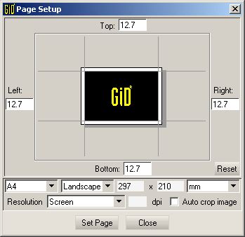
Page setup window
Window to set up some print properties (page size, borders,etc.) and image properties
(image resolution and Auto crop image option).
This settings are applied when sending an image to printer (see section Print), or to a file (see section Print to file).
|
|
![]()
Send the current image to the selected printer
Recent files |
![]()
User can access quickly to the recent files opened previously with GiD.
Quit |
![]()
![]()
![]()
Command Quit is used to finish the working session. If there were
changes since the last time a session was saved, GiD asks the user to save them.
Go to the first, previous, next, last section, table of contents.