USER BASICS |
The following features are essential to the effective use of the GiD system. They are, therefore, described apart from the pre-processing facilities section.
Point definition |
Many functions inside GiD need the definition of a point to be given by the user. Points are the lowest level of geometrical entity and, therefore the most commonly used. It is, consequently, important that the user has a thorough understanding of their definition and uses. Sometimes an existing point is required and sometimes a new or an old point must be defined.

Entering coordinates window
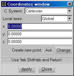
All the options explained in this section are available through the specific window
of Points Definition (see section Coordinates window). This window is accessed via the
options Utilities and Tools in the title's bar. In doing so, the user
can choose not only the kind of reference system, cartesian, cylindrical or spherical,
but also the system to be used, global or local and if the origin of coordinates is
fixed or relative (new coordinates are referred to the last entered origin point).
In the most general case the user can enter points in the following ways:
- Picking in the graphical window.
- Entering points by coordinates.
- Selecting an existing point.
- Button
Base.
Picking in the graphical window |
Points are picked in the graphics window in the plane z=0 according to the coordinates viewed in the window. Depending on the activated preferences (see section Preferences), if the user selects a region located in the vicinity of an existing point, GiD asks whether it should create a new point or if it should use the existing one.
Entering points by coordinates |
GiD offers a window for entering points in order to easily create geometries, defining fixed or relative coordinates as well as different reference systems, cartesian, cylindrical or spherical.
Coordinates of the point can be entered either in the enter points window
or in the command line by following one of two possible formats:
-
In the format:
x,y,z -
In the format:
x y z
Coordinate z can be omitted in both cases. The following are valid examples of point definitions:
	5.2,1.0         5.2,1
	8 9 2           8 9,2
All the point's coordinates can be entered as local or global and through different reference systems in addition to the cartesian one.
- Local/global coordinates
- Cylindrical coordinates
- Spherical coordinates
Local/global coordinates |
Local coordinates are always considered relative to the last point that was used,
created or selected.
It is possible to use the commands Utilities and Id in order to make a
reference to one point (see section Id). Then, to define points using local coordinates
referring to the same point, use Options and Fixed Relative
when entering each point. The last point selected or created before using this
will be the origin of the local coordinate system. It is also possible to enter this
central point by its coordinates.
The following are valid examples of defining points using local coordinates:
	Example (1):
				1,0,0
				@2,1,0 (actual coordinates 3,1,0)
				@0,3,0 (actual coordinates 3,4,0)
				2,2,2
				@1,0,3 (actual coordinates 3,2,5)

	Example (2):
				1,0,0
				Fixed Relative (when creating the point)
				@2,1,0 (actual coordinates 3,1,0)
				@0,3,0 (actual coordinates 1,3,0)
				2,2,2
				@1,0,3 (actual coordinates 2,0,3)

	Example (3):
				'local_axes_name'2.3,-4.5,0.0
The last example shows how to enter a point from a local coordinate system called
'local_axes_name' (any name inside the quotation marks will fit), previously
defined via the option define local axes (see section Local axes).
All the examples have been presented using a cartesian notation. However, cylindrical or spherical coordinates can also be used.
Cylindrical coordinates |
Cylindrical coordinates can be entered as: r<angle,z
The z_coordinate may be omitted and angles are defined in degrees. Cylindrical coordinates can be applied to global and local coordinate systems.
The following are valid examples of the same point definitions:
	example (1):
				1,0,0
				1.931852<15

	example (2):
				1,0,0
				@1.0<30
Spherical coordinates |
Spherical coordinates can be entered as r<anglexy<anglez
Anglez may be omitted and angles are defined in degrees. Spherical
coordinates can be applied to global and local coordinate systems.
The following are valid examples of the same point definitions:
	Example (1):
				1,0,0
				1.73205<18.43495<24.09484

	Example (2):
				1,0,0
				@1.0<45<45
Option Base |
![]()
If button Base is selected (button is set on No Base), a point
can be retrieved from any of the other modes. Then, the coordinates of this point,
instead of being used, are written in the command line and can be edited before
entering it.
It is possible to change the default way that GiD works with points via preferences (see section Preferences).
Selecting an existing point |
![]()
When the user is inside a function that asks for a point, GiD can be in one of the
two modes: entering a new point or selecting and old one. They can be distinguished
by the cursor that will be either a cross or a box. To change from the first mode
to the second one, the user must select button join from the right
side column commands or its shortcut (Control-a).
This button is then set to No Join. After this, select an existing
point to get it. (Control-a) switches from Join to No Join and
vice versa.
Options Join and No join can also be obtained from the
Contextual submenu in the 3rd button menu (see section Mouse operations).
Special options FJoin and FNoJoin force GiD to change either
to Join mode or No join mode independently of the previous mode.
Option point in line |
![]()
By using this option, the user can pick over a line in the graphical window. One point will be created over the line in the position where the user has picked.
Option point in surface |
![]()
By using this option, the user can pick over a surface in the graphical window. One point will be created over the surface in the position where the user has picked.
Option tangent in line |
![]()
By using this option, the user can pick over a line in the graphical window. One vector will be returned that is the tangent to the line in the position where the user has picked.
Option normal in surface |
![]()
By using this option, the user can pick over a surface in the graphical window. One vector will be returned that is the normal to the surface in the position where the user has picked.
Option Arc center |
![]()
By using this option, the user can pick over an arc in the graphical window. One point will be returned in the center of the arc selected.
Grid |
![]()
It is possible to use an auxiliar grid of lines to easily define 2D points. Can be activated the 'snap',
to force points to be in grid intersections.
From the preferences window (see section Preferences) is possible to set the separation between lines, to show the coordinates origin, extents, etc.
There is a small button on the rigth-down corner to activate or deactivate the grid and snap.
Entities selection |
Many commands need some entities to be selected before applying them, and the
method of selection is always identical. Before selecting entities, the user
is prompted to decide whether to select points, lines, surfaces or volumes (in
some cases this decision is obvious or it is made within the context of the
option).
Within one of the generic groups (points, lines, surfaces, volumes, nodes or
elements), it does not matter what type of
entity is selected (for example, an arc or a spline, both line entities are
selected in the same way). After this, if one entity of the desired group is
selected, it is colored red to indicate its selection and the user is
prompted to enter more entities. If the user selects away from any entity, a
dynamic box is opened that can be defined by picking again in another place.
All entities that are either totally or partly within this box are selected.
Next, the user is prompted to enter more entities. The normal selection mode
is SwapSelection: If one entity is selected a second time, it becomes
deselected and its color reverts to normal, It also exist the options AddToSelection
and RemoveFromSel to only add or only remove entities to the selection.
Note: Instead of picking twice to begin and end the selection box, it is
possible to keep left mouse pressed and move the cursor.
Option Clear selection found in the Contextual mouse menu, deselects all previously selected entities.
It is also possible to select entities by entering their label in the command
line. For instance, to select the entity with number 2, the user has to input
this number, 2, in the command line. To select the entities 3 to 7,
the user has to input 3:7 in the command line. Option 3: will
select all entities from number 3 to end and option :3 will select all
options from beginning to number 3.
If a layer named ll1 exists, it is possible to select all entities belonging
to that layer with command: layer:ll1 . Using command layer:
select all entities belonging to no layer.
Another way of selecting points or nodes is to write:
plane:a,b,c,d,r
Where a,b,c,d and r are real numbers that define a plane and a tolerance in the
following way: ax+by+cz+d<r.
Points close to that plane are chosen.
In some commands, another item is added to the selection group. This item, called AllTypes, means to select all entities levels (points...volumes) at the same time.
In this case, only selection via a dynamic box is possible in the graphical window and all entities (points, lines, surfaces and volumes) in the box are selected.
To finish the entities selection, use escape (see section Escape).
If the option Fast Selection is used, entities are not
colored red when selected and choosing an entity twice does not deselect it. Option Fast Selection is available in the right buttons (see section Tools), in Utilities > Variables.
Caution: Use only Fast Selection when needing to select a
large amount of entities, for example in a large mesh. The possibility of
repeating entities within the selection is dangerous.
Entities belonging to frozen layers (see section Layers) are not taken into account
in the selection. Entities belonging to OFF layers cannot be selected directly
in the graphical window, but can be selected by
giving its number or giving a range of numbers.
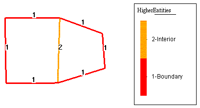
It is possible to add filters to the selection that, after selecting some entities, only remains selected the ones that accomplish with the filter criteria. To enter one filter must write in the command line the word filter: and one option. Options are:
- HigherEntity
- MinLength
- MaxLength
- EntityType
- BadMinAngle
- BadMaxAngle
Note: To apply selection filters you can also use the Selection window (see section Selection window).
Note: MinLength and MaxLength can be used either in the
geometry lines or in elements of the mesh.
Example:
filter:HigherEntity=1
Means that only the entities that have higher entity equal to one will be selected.

Note: A typical use of filter is to select only boundary lines (higherentiety=1).
Quit |
![]()
![]()
![]()
Command Quit is used to finish the working session. If there were
changes since the last time a session was saved, GiD asks the user to save them.
Escape |
The command escape is used for moving up a level within the right side
column menus, for finishing most commands, or for finishing selections and other
utilities. This command can be applied by:
- Middle button of the mouse.
-
Key
ESC. -
Button
escapein the right side commands menu. -
Writing the reserved word
escapein the command line. This is useful in scripts (see section Batch file).
All above options give the same result.
Caution: escape is a reserved word. It cannot be used in any
other context.
Go to the first, previous, next, last section, table of contents.