CUSTOMIZATION |
Introduction |
When GiD is to be used for a particular type of analysis, it is necessary to predefine all the information required from the user and to define the way the final information is given to the solver module. To do so, some files are used to describe conditions, materials, general data, units systems, symbols and the format of the input file for the solver. We call Problem Type to this collection of files used to configure GiD for a particular type of analysis.
Note: You can also learn how to configure GiD for a particular type of analysis, following the Problem Type Tutorial; this tutorial is included with the GiD package you've bought. You can also download it from the GiD web page. (http://www.gidhome.com/support)
Due to the vocation of GiD as general-purpose pre and post processor, the configuration for the different analysis must be performed according to the particular specifications of every solver. This implies the necessity of creating specific data input files for every solver. However, GiD allows to performing this configuration process inside itself without any change in the solver and without having to program any independent utility.
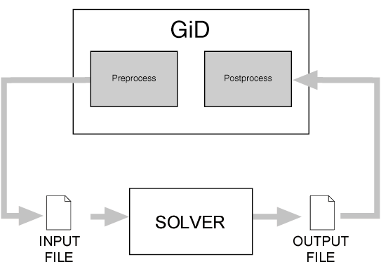
To configure these files means to define the data that must be input by the user, as well as the materials to be implemented and other geometrical and time-dependent conditions. It is also possible to add some symbols or drawings to represent the defined conditions. GiD gives the opportunity of working with units when defining the properties of the mentioned data, but there must be a configuration file where it could be found the definition of the units systems.It must be also defined the way that all this data must be written inside a file that will be the input file to be read by the corresponding solver.
The creation of a Problem Type implies the creation of a directory
with the Problem's Type name and the extension .gid. This
directory can be located in the current working directory or in the
main GiD executable directory. The first case, the creation inside
the current working directory, can be useful during the development of
the project. Once it is finished, it can be advisable to move the
directory to the one where GiD is stored; like this, your Problem Type
will be added to those included in the system and it will appear in
the GiD menu (see section Problem type). In both cases, the series of
files must be inside the problem type directory. The name for most of
them will be composed by the same problem type's name and an extension
referring to their function. Considering problem_type_name to
be the name of the Problem Type and project_name the name of
the project, the diagram of the file configuration is the following:
- directory name:
problem_type_name.gid - directory location:
c:\a\b\c\GiD_directory\problemtypesNote: In versions previous to 6.0 theproblemtypesdirectory does not exist, so your problem type must reside in theGiD_directory. In versions later to 6.0 it's recommended to put your problem type inside theproblemtypesdirectory. - Configuration files
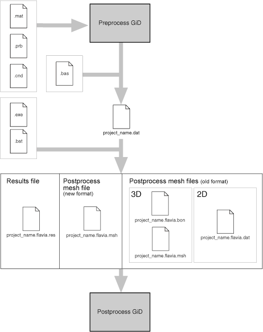
problem_type_name.xmlXML based configurationproblem_type_name.cndConditions definitionsproblem_type_name.matMaterials propertiesproblem_type_name.prbProblem and intervals dataproblem_type_nameuniUnits Systemsproblem_type_name.simConditions symbols***.geoSymbols geometrical definitions***.geoSymbols geometrical definitions ...
- Template files
problem_type_name.basInformation for the data input file***.basInformation for additional files***.basInformation for additional files ...
- Tcl extension files
problem_type_name.tclExtensions to GiD written in the Tcl/Tk programming language
- Command execution files
problem_type_name.batOperating system shell that executes the analysis process
Files problem_type_name.sim, ***.geo and ***.bas
are not mandatory and can be added to facilitate the visualization
(files problem_type_name.sim and ***.geo) or to prepare
the data input for the restart in additional files (files
***.bas). In the same way problem_type_name.xml is not
necessary, it can be used to customize features such as: version info,
icon identification, password validation, etc.
Configuration Files |
These files generate the conditions and material properties, as well as the proper general problem and intervals data to be transferred to the mesh, giving at the same time the chance to define geometrical drawings or symbols to represent some conditions on the screen.
XML file |
The file <problem type>.xml contains information related with
the configuration of the problem type such as file browser, icon,
password validation or message catalog location. Besides this file can
be used for the problem type in order to store assorted structured
infomation such as version number, news added from the last version,
and whatever the developer decide to include. This file can be read
using the tcl extension tcom which is provided with
GiD.
The data included inside the xml file should follow the following structure:
<Infoproblemtype version="1.0">
<Program>
</Program>
</Infoproblemtype>
We suggest to include the following nodes (the value of the nodes are just examples):
<Name>Nastran 2.4</Name>to provide a long name for the problem type<Version>2.4</Version>dotted version number of the problem type.<MinimumGiDVersion>7.5.1b</MinimumGiDVersion>minimun GiD version required.-
<ImageFileBrowser>images/ImageFileBrowser.gif</ImageFileBrowser>icon image to be used in the file browser to show a project corresponding to this problem type. It is recommended to use the dimension17x12pixels for this image. <MsgcatRoot>scripts/msgs</MsgcatRoot>a path, relative or absolute indicating where the folder with namemsgsis located. The foldermsgscontains the messages catalog for translation.<PasswordPath>..</PasswordPath>a path, relative or absolute, indicating where to write the password information. See section ValidatePassword node.<ValidatePassword> </ValidatePassword>provide a custom validation script in order to overide the default GiD validation. See see section ValidatePassword node.
ValidatePassword node |
The default behaviour taken by GiD when validating a problem
type password if verifying if it is not empty. Also when a password is
considered as valid then this information is writen in the file
password.txt where the file is located relative to the problem type
directory. In order to override this behaviour 2 nodes are provided in
the .xml file
- PasswordPath: the value of this node specify a relative or
absolute path where to locate/create the file
password.txt. If the value is a relative path it is taken with respect to the problem type path. Example:<PasswordPath>..</PasswordPath>
- ValidatePassword: the value of this node is a tcl script which
will be executed when a password for this problem type need to be
validated. The script receive the parameters for the validation in the
variables
keywith the contents of the password typed,dirwith the path of the problem type, andcomputernamewith the name of host machine. The script should return 3 possible codes: 0 in case of failure, 1 in case of success and 2 in case of success, the difference here is that the problem type has just saved the password information so GiD should not do it. Besides we can provide a description of the status returned for GiD to show it to the user. If other status is returned it is assumed 1 as default. Below is an example of a<ValidatePassword>node.<ValidatePassword> #validation.exe simulates an external program to validade the key for this computername #instead an external program can be used a tcl procedure if { [catch {set res [exec [file join $dir validation.exe] $key $computername]} msgerr] } { return [list 0 "Error $msgerr"] } switch -regexp -- $res { failRB { return [list 0 "you ask me to fail!"] } okandsaveRB { proc save_pass {dir id pass} { set date [clock format [clock second] -format "%Y %m %d"] set fd [open [file join $dir .. "password.txt"] "a"] puts $fd "$id $pass # $date Password for Problem type '$dir'" close $fd } save_pass $dir $computername $key rename save_pass "" return [list 2 "password $key saved by me"] } okRB { return [list 1 "password $key will be saved by gid"] } default { return [list 0 "Error: unexpected return value $res"] } } </ValidatePassword>
Conditions file (.cnd) |
The file with extension's name .cnd contains all the
information about the conditions that can be applied to different
entities. The condition can adopt different field values for every
entity. This type of information includes, for instance, all the
displacement constraints and applied loads in a structural problem or
all the prescribed and initial temperatures in a thermical analysis.
An important characteristic of the conditions is that they must
define over what kind of entity are going to be applied, i.e., over
points, lines, surfaces, volumes or layers and over what kind of
entity will be transferred, i.e., over nodes, over face elements or
over body elements.
- over nodes means that the condition will be transferred to the nodes contained in the geometrical entity where condition is assigned.
- over face elements ?multiple? If this condition is applied to a line that
is the boundary of a surface or to a surface that is the boundary of a
volume, this condition is transferred to the higher elements, marking
the affected face.
If optionally it is declared as multiple then can be transferred to more than one element face if exists. By default it is considered like single, and only one element face will be marked. - over body elements If this condition is applied to lines, it will be transferred to line elements. If it is assigned to surfaces, it will be transferred to surface elements. If in volumes, to volume elements.
Note: For backwards compatibility, it is accepted the
possibility over elements, that will transfer either to elements
or to faces of higher level elements.
Another important feature is that all the conditions can be applied to different entities with different values for all the defined intervals of the problem.
Therefore, a condition can be considered as a group of fields containing the name of the referred condition, the geometric entity over which it is applied, the mesh entity over which it will be transferred, its corresponding properties and their values.
The format of the file is as follows:
CONDITION: condition_name
CONDTYPE: 'over' ('points', 'lines', 'surfaces', 'volumes', 'layer')
CONDMESHTYPE: 'over' ('nodes', 'face elements','face elements multiple', 'body elements')
QUESTION: field_name['#CB#'(...,optional_value_i,...)]
VALUE: default_field_value
  ...
QUESTION: field_name['#CB#'(...,optional_value_i,...)]
VALUE: default_field_value
END CONDITION

CONDITION: condition_name
  ...
END CONDITION
Note: #CB# means Combo Box.
Note that this file format does not permit to put blank lines between
the last line of a condition definition, END CONDITION, and the
first one of the next condition definition.
Local Axes
QUESTION: field_name['#LA#'('global', 'automatic', 'automatic alternative')]
VALUE: default_field_value
This type of field makes reference to the local axes system to be used. The position of the values indicates the kind of local axes.
If it only has a single default value, this will be the name of the global axes. If two values are given, the second one will reference a system that will be automatically computed for every node and that will depend on the geometric constraints, like tangencies, orthogonalities, etc. If a third value is given, it will be the name of the automatic alternative axes, which are the automatic axes rotated 90 degrees.
All the different user defined systems will be added automatically to these default possibilities.
To enter only a specific kind of local axes it's possible to use the modifiers #G#,#A#,#L#.
-
#G#: global axes -
#A#: automatic axes -
#L#: automatic alternative axes
When using these modifiers the position of the values doesn't indicate the kind of local axes.
Example
QUESTION: Local_Axes#LA#(Option automatic#A#,Option automatic_alt#L#)
VALUE: -Automatic-
Note: All the fields must be fulfilled with words, considering as a word a character string without any blank space amongst them. The strings
signaled between quotes are literal and the ones inside brackets are
optional. The interface is case-sensitive, so the uppercase letters must
be maintained. Default_field_value and different
optional_value_i can be alphanumeric, integers or reals. GiD
treats them as alphanumeric until the moment that are written to the
solver input files.
Note: The numbers of the conditions must be consecutive, beginning with number 1. There is no need to point out the overall number of conditions or the respective number of fields for each one. This last one can be variable for each condition.
One optional flag to add to a condition is:
CANREPEAT: yes
It is written after CONDMESHTYPE and means that user can assign one condition several times to the same entity.
Another type of field that can be included inside a condition is:
QUESTION: Surface_number#FUNC#(NumEntity)
VALUE: 0
Where the key #FUNC#, means that the value of this field will be
calculated just when the mesh is generated. It can be considered a
function that evaluates when meshing. In the example above,
NumEntity is one of the possible variables of the function. It
will be substituted by the label of the geometry entity from where the
node or element is generated.
QUESTION: X_press#FUNC#(Cond(3,REAL)*(x-Cond(1,REAL))/(Cond(2,REAL)-Cond(1,REAL)))
VALUE: 0
In this second example, x variable is used, which means the
x-coordinate of the node or of the center of the element. Others fields
of the condition can also be used in the function. Variables y
and z give the y ans z-coordinate of this point.
Note: There are other available options to expand the capabilities of the conditions window. (see section Special fields)
Example: Creating the conditions file |
Next is an example of a condition file creation, explained step by step:
- First, you have to create the folder or directory where all the problem type
files are located,
problem_type_name.gid/on this case. - Then create and edit the file (
problem_type_name.cndon this example) inside the recently created directory (where all your problem type files are located). As you can see, except for the extension, the name of the file and the directory are the same. - Create the first condition, which starts with the line
CONDITION: Point-Constraints
The parameter is the name of the condition. A unique condition name into this condition file is required. - This first line is followed by the next pair:
CONDTYPE: over points
CONDMESHTYPE: over nodes
which declare over what entity is going to be applied the condition. The first line,CONDTYPE:...refers to the geometry, and may take as parameters the sentences "over points", "over lines", "over surfaces" or "over volumes".The second line refers to the type of condition applied to the mesh, once generated. GiD does not force to provide this second parameter, but if it is present, the treatment and evaluation of the problem will be more acurate. The available parameters for this statement are "over nodes" and "over elements".
- Then, you'll have to declare a set of questions and values applied to this condition.
QUESTION: Local-Axes#LA#(-GLOBAL-)
VALUE: -GLOBAL-
QUESTION: X-Force
VALUE: 0.0
QUESTION: X-Constraint:#CB#(1,0)
VALUE: 1
QUESTION: X_axis:#CB#(DEFORMATION_XX,DEFORMATION_XY,DEFORMATION_XZ)
VALUE: DEFORMATION_XX

END CONDITION
After the QUESTION: word you have the choice of put:- An alphanumeric field name followed by the #LA# statement, and then the single or double parameter.
- An alphanumeric field name.
- An alphanumeric field name followed by the #CB# statement, and then the optional values between parenthesis.
The VALUE: word must be followed by one of the optional values, if you have declared them in the previous QUESTION: line. If you don't follow this statement, the program may not work correctly.
In the previous example, the
X-ForceQUESTION takes the value 0.0. Also in the example, theX-ConstraintQUESTION includes a combo box statement (#CB#), followed by the declaration of the choices 1 and 0. In the next line, the value takes the parameter 1. TheX_axisQUESTION declares three items for the combo boxDEFORMATION_XX,DEFORMATION_XY,DEFORMATION_XZ, with the valueDEFORMATION_XXchosen.Beware of leaving blank spaces between parameters. If in the first question, you put the optional values
(-GLOBAL, -AUTO-), (note the blank space after the comma), there will be an error when reading the file. Take this precaution specially in the Combo Box question parameters, to avoid unpredictable parameters. - The management of the conditions defined in the
.cndfile, is done in the Conditions window (found in the Data menu), in the preprocess of GiD.
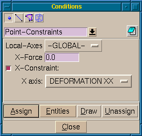
Conditions edition window on Preprocess, showing an unfolded combo box
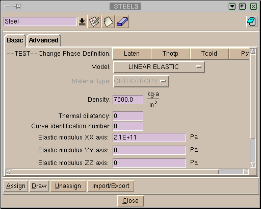
Materials file (.mat) |
This file NAME.mat include originally the definition of different materials
through their properties. These are base materials as they can be used as templates
during the pre-processing step for the creation of newer ones.
The user can define as many materials as desired and with a variable number of fields. All the unused materials will not be taken in consideration when writing the data input files for the solver. Alternatively, they can be useful to generate a materials library.
Conversely to the case of conditions, the same material can be assigned to different geometrical entities levels (lines, surfaces or volumes) and even can be assigned directly to the mesh elements.
In a similar way as a condition was defined, a material can be considered as a group of fields containing its name, its corresponding properties and their values.
The format of the file is as follows:
MATERIAL: material_name
QUESTION: field_name['#CB#'(...,optional_value_i,...)]
VALUE: default_field_value
  ...
QUESTION: field_name['#CB#'(...,optional_value_i,...)]
VALUE: default_field_value
END MATERIAL

MATERIAL: material_name
  ...
END MATERIAL
If a property of a material change depending on something (one example would be one property depending on the temperature and defined with several values for several temperatures), a table of changing values may be declared for this property. When the solver evaluates the problem, it reads the values and apply the suitable property value.
The declaration of the table requires a pair of lines:
First, a QUESTION line with a list of alphanumeric values between parenthesis.
QUESTION: field_name:(...,optional_value_i,...)
This values are the name of each of the columns in the table, and the number of values declared are the number of columns.
This first line is followed by the actual data declaration: a line started with the words
VALUE: #N# is followed by a number that indicates the quantity of elements
in the matrix and, finally, the list of values.
VALUE: #N# number_of_values ... value_number_i ...
The number of values declared for the matrix, obviously, has to be the multiplication of the number of columns by the number of rows to be declared.
The usual case of application of this declaration is on the thermo-mechanical simulations, where the problem is exposed to a temperature variation, and the properties of the materials change for each temperature value.
All the fields must be filled with words, considering a word as a character string
without any blank space amongst them. The strings signaled between quotes are literal
and the ones within brackets are optional. The interface is case-sensitive, so the
uppercase letters must be maintained. Default_field_value and different
optional_value_i can be alphanumeric, integers or reals, depending on the type.
The numbers of the materials have to be consecutive, beginning with number 1. There is no need to point out the overall number of materials or the respective number of fields for each one. This last one can be variable for each material.
Note that in this file it's not permitted the inclusion of blank lines between material definitions neither between questions and values.
Note: There are other available options to expand the capabilities of the materials window. (see section Special fields)
Example: Creating the materials file |
Next is an example of a materials file creation, explained step by step:
- Create and edit the file (
problem_type_name.maton this example) inside theproblem_type_namedirectory (where all your problem type files are located). As you can see, except for the extension, the name of the file and the directory are the same. - Create the first material, which starts with these lines:
MATERIAL: Air
The parameter is the name of the material. A unique material name into this material file is required (do not use blank spaces in the name of the material.) - The next two lines define a property of the material and its default value:
QUESTION: Density
VALUE: 1.0
You can add as many properties as you want. To end the material definition, add the following line:END MATERIAL
- In this example we have introduced some materials; the
.matfile would be as follows:MATERIAL: Air QUESTION: Density VALUE: 1.01 END MATERIAL MATERIAL: Steel QUESTION: Density VALUE: 7850 END MATERIAL MATERIAL: Aluminium QUESTION: Density VALUE: 2650 END MATERIAL MATERIAL: Concrete QUESTION: Density VALUE: 2350 END MATERIAL MATERIAL: Water QUESTION: Density VALUE: 997 END MATERIAL MATERIAL: Sand QUESTION: Density VALUE: 1370 END MATERIAL
- The management of the materials defined in the
.matfile, is done in the Materials window (found in the Data menu), in the preprocess of GiD.
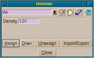
Materials edition window on the GiD Preprocess
Problem and intervals data file (.prb) |
The file NAME.prb contains all the information about the general problem
and intervals data.
The general problem data is all the information required for performing the
analysis and it does not concern any particular geometrical entity. This differs from
the previous definitions of conditions and materials properties, which are
assigned to different entities. Example of general problem data can be the type of solution
algorithm used by the solver, the value of the various time steps,
convergence conditions and so on.
Within this data, the user may consider the definition of specific problem data (for the whole process) and intervals data (variable values along the different solution intervals). An interval would be the subdivision of a general problem that contains its own particular data. Typically, one can define a different load case for every interval or, in dynamic problems, not only variable loads, but also changing the various time steps, convergence conditions and so on.
The format of the file is as follows:
PROBLEM DATA
QUESTION: field_name['#CB#'(...,optional_value_i,...)]
VALUE: default_field_value
  ...
QUESTION: field_name['#CB#'(...,optional_value_i,...)]
VALUE: default_field_value
END PROBLEM DATA

INTERVAL DATA
QUESTION: field_name['#CB#'(...,optional_value_i,...)]
VALUE: default_field_value
  ...
QUESTION: field_name['#CB#'(...,optional_value_i,...)]
VALUE: default_field_value
END INTERVAL DATA
All the fields must be filled with words, considering a word as a character string
without any blank space amongst them. The strings signaled between quotes are literal
and the ones inside brackets are optional. The interface is case-sensitive, so the
uppercase letters must be maintained. Default_field_value and different
optional_value_i can be alphanumeric, integers or reals, depending on the type.
Note: There are other available options to expand the capabilities of the Problem Data window. (see section Special fields)
Example: Creating the PRB data file |
Next is an example of a problem data file creation, explained step by step:
- Create and edit the file (
problem_type_name.prbon this example) inside theproblem_type_namedirectory (where all your problem type files are located). Except for the extension, the name of the file and the directory must be the same. - Start the file with this line:
PROBLEM DATA
- Then, add the following lines:
QUESTION: Unit_System#CB#(SI,CGS,User)
VALUE: SI

QUESTION: Title
VALUE: Default_title
The first question defines a combo style menu calledUnit_System, which has theSIoption selected by default. The second question defines a text field calledTitle, and its default value isDefault_title. - To finish the file, add the following line:
END PROBLEM DATA
- The whole file is as follows:
PROBLEM DATA
QUESTION: Unit_System#CB#(SI,CGS,User)
VALUE: SI
QUESTION: Title
VALUE: Default_title
END GENERAL DATA
- The management of the options defined in the
.prbfile, is done in the Problem Data window (found in the Data menu), in the preprocess of GiD.
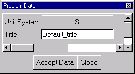
Problem Data window on the GiD Preprocess
Conditions symbols file (.sim) |
This file NAME.sim comprises different symbols to represent some conditions
during the pre-processing stage. The user may define these symbols by creating,
ad hoc, geometrical drawings and the appropriate symbol will appear
over the entity with the applied condition every time the user asks for it.
One or more symbols can be defined for every condition and the selection will depend on the specified values in the file, which may be obtained through mathematical conditions.
Also the spatial orientation can be defined in this file, depending on the values taken by the required data. For global definitions, the user must input the three components of a vector to express its spatial direction. GiD takes these values from the corresponding conditions window. The orientation of the vector can be understood as the rotation from vector (1,0,0) towards the new vector defined in the file.
For line and surface conditions, the symbols may be considered as local. In this case, GiD does not consider the defined spatial orientation vector and it takes its values from the line or surface orientation. The orientation assumes vector (1,0,0) to be the corresponding entity's normal.
These components, making reference to the values obtained from the adequate conditions,
may include C-language expressions. They express the different field values of the
mentioned condition as cond(type,i), where type (real or int)
makes reference to the type of variable (independent of the letters case) and
i is the number of the field for that particular condition.
Example: Creating the Symbols file |
Next is an example of a symbol file creation.
Create and edit the file (problem_type_name.sim on this example) inside
the problem_type_name directory (where all your problem type files are located).
Except for the extension, the name of the file and the directory must be
the same.
The contents of the problem_type_name.sim example should be the following:
cond Point-Constraints
3
global
cond(int,5)
1
0
0
Support3D.geo
global
cond(int,1) && cond(int,3)
1
0
0
Support.geo
global
cond(int,1) || cond(int,3)
cond(int,3)
cond(int,1)*(-1)
0
Support-2D.geo
cond Face-Load
1
local
fabs(cond(real,2))+fabs(cond(real,4))+fabs(cond(real,6))>0.
cond(real,2)
cond(real,4)
cond(real,6)
Normal.geo
This is a particular example of the file .sim where the user has defined four
different symbols. Each one is read from a file ***.geo. There is no indication of
how many overall symbols are implemented. GiD simply reads all the file long through the
end.
The files ***.geo are obtained through GiD. The user may design a
particular drawing to symbolize a condition and this drawing will be stored as
PROBLEMNAME.geo when saving this project as PROBLEMNAME.gid.
The user needs not to be concerned about the symbol
size but has to keep in mind that the origin corresponds to the point (0,0,0) and
the reference vector is (1,0,0). Subsequently, when these files ***.geo are
invoked from problem_type_name.sim, the symbol drawing, appears
scaled on the display, at the entities location.
Nevertheless, the number of symbols and consequently, the number of files ***.geo, can
vary from a condition to another. In the previous example, for instance, the condition called
Point-Constraints, which is so declared by the use of cond, comprises three
different symbols. GiD knows that from the number 3 written below the condition's name. Next,
GiD reads if the orientation is relative to the spatial axes (global) or
moves together with its entity (local). In the example, the three symbols concerning
point constraints are globally oriented.
Let's imagine that this condition has six fields. First, third and fifth field values express
if there exist constraints along X-axis, Y-axis and Z-axis, respectively.
These values are integers and in case they were null, the concerned degree of freedom
would be assumed to be unconstrained.
For the first symbol, got from the file Support3D.geo, GiD reads
cond(int,5), or Z-constraint. If it is false, what means that the field's
value is zero, the C-condition will not be accomplished and
GiD will not draw it. Otherwise, the C-condition will be accomplished and the symbol
will be invoked. When this occurs, GiD skips the rest of symbols related to this
condition. Its orientation will be the same of the original drawing because
the spatial vector is (1,0,0).
All the considerations are valid for the second symbol, got from the file Support.geo,
but now GiD has to check that both constraints (&&), X-constraint
and Y-constraint are fixed (values different from zero).
For the third symbol, got from the file Support-2D.geo, only one of them has to be
fixed (||) and the orientation of the symbol will
depend on which one is free and which one is fixed, showing on the screen the
corresponding direction for both degrees of freedom.
Finally, for the fourth symbol, got from the file Normal.geo, it can be observed
that the drawing of the symbol, related to the local orientation
will appear scaled according to the real-type values of the second, fourth and sixth
fields values. Different ways of C-language expressions are available in GiD.
Thus, the last expression would be equivalent to put '(fabs(cond(real,2))>0. ||
fabs(cond(real,4))!=0. || fabs(cond(real,6))>1e-10)'.
Note: As previously mentioned, GiD internally creates a PROJECTNAME.geo when
saving a project, where it keeps all the information about the geometry
in binary format. In fact, this is the reason why the extension of these files is
.geo. However, the file PROJECTNAME.geo is stored in the
PROJECTNAME.gid directory, whereas these user-created files ***.geo are
stored in the problem_type_name.gid directory, being problem_type_name the problem's name.
Unit System file (.uni) |
When GiD is installed, the file units.gid is copied within the GiD
directory. In this file it's defined a table of magnitudes. For each
magnitude there is a set of units and a conversion factor between the
unit and the reference unit. Also are defined the units systems. An unit
system is a set of mangnitudes and the corresponding unit.
BEGIN TABLE
 LENGTH : m {reference}, 100 cm, 1e+3 mm
 ...
 STRENGTH : kg*m/s^2 {reference}, N, 1.0e-1 kp
END

BEGIN SYSTEM(INTERNATIONAL)
 LENGTH : m
 MASS : kg
 STRENGTH : N
 ...
 TEMPERATURE : C
END
The syntax of the unit file (problem_type_name.uni) within the problem type is similar.
Besides, it could include the line:
USER DEFINED: ENABLED
(or DISABLED)
meaning that the user is able (or not) to define it's own system unit
within the project. If the line does not appear in the file then, it's
assumed as having the value ENABLED
It is possible to ignore all units systems defined by default inside the file units.gid:
USE BASE SYSTEMS: DISABLED
(or ENABLED)
Some magnitudes can be hidden to the user in the units window with this order:
HIDDEN: 'magnitude', 'magnitude'
HIDDEN: strength, pressure
If the problem type uses a property which has a unit, then GiD creates the file project_name.uni in the project directory. This file includes the information related to the unit used in the geometric model
and the unit system used. The structure of this file is:
MODEL: km

PROBLEM: USER DEFINED

BEGIN SYSTEM
 LENGTH: m
 PRESSURE: Pa
 MASS: kg
 STRENGTH: N
END
In this file, MODEL refers to the unit of the geometric model, PROBLEM is the name of the units system used by GiD to convert all the data properties in the output to the solver. If this name is USER DEFINED, then the system is the one defined within the file. The block
BEGIN SYSTEM
 ...
END
corresponds to the user defined system.
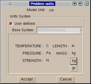
Data unit window
Special fields |
These fields are useful in order to organize the information within the data files. They make the information showed on the data windows nicest and more readable. In this way the user can concentrate just on the data properties concerning the current context.
- Book:
With the field Book it is possible to split the data windows in other
windows. For example, we can have two windows for the materials, one for
the steels and another for the concretes:
BOOK: Steels
...
All steels come here
...
BOOK: Concretes
...
All concretes come here
...
Options corresponding to books
- Title:
The Title field groups a set of properties on different tabs of one
book. All properties appearing after this field will be included on this
tab.
TITLE: Basic
...
Basics properties
....
TITLE: Advanced
...
Advanced properties
...
Book with title
- Help:
With the Help field it's possible to assign a description to the data
property preceding it. In this way the user can inspect the meaning of the
property through the help context function: staying for a while with the
mouse on the property or clicking the right button.
QUESTION: X_flag#CB#(1,0)
VALUE: 1
HELP: If this flag is set, movement is ...
Data property with help
- Image:
The Image field is useful to insert descriptive pictures on the data
window. The value of this field is the file name of the picture relative
to the problem type location.
IMAGE: omega3.gif
Data window with an image
- Unit field:
With this feature it's possible to define and work with
properties having units. GiD is responsible for the conversion
between units of the same magnitude.
...
QUESTION: Elastic modulus XX axis:#UNITS#
VALUE: 2.1E+11Pa
...
Data property with unit.
- Dependencies: Depending on the value, we can define some behaviour associated to the property. For each value we can have a list of actions. The syntax is as follows:
DEPENDENCIES:(<V1>,[TITLESTATE,<Title>,<State>],<A1>,<P1>,<NV1>,...,<An>,<Pn>,<NVn>)...(<Vm>,<Am>,<Pm>,<NVm>,...)
where:- <Vi> is the value that triggers the actions. A special value is #DEFAULT#, which refers to all the values not listed.
-
[TITLESTATE,<Title>,<State>] this argument is optional. Titlestate should be used to show or hide book labels. Many Titlestate can be given. <Title> is the title defined for a book (TITLE: Title). State is the visualization mode:
normalorhidden. - <Ai> is the action and can have one of these values: SET, HIDE, RESTORE. All these actions change the value of the property with the following differences: SET disables the property, HIDE hides the property and RESTORE brings the property to the enabled state.
- <Pi> is the name of the property to modify.
- <NVi> is the new value of <Pi>. A special value is #CURRENT#, which refers to the current value of <Pi>.
...
TITLE: General
QUESTION: Type_of_Analysis:#CB#(FILLING,SOLIDIFICATION)
VALUE:  SOLIDIFICATION
DEPENDENCIES: (FILLING,TITLESTATE,Filling-Strategy,normal,RESTORE,
Filling_Analysis,GRAVITY,HIDE,Solidification_Analysis,#CURRENT#)
DEPENDENCIES: (SOLIDIFICATION,TITLESTATE,Filling-Strategy,hidden,HIDE,
Filling_Analysis,#CURRENT#,RESTORE,Solidification_Analysis,#CURRENT#)
TITLE: Filling-Strategy
QUESTION: Filling_Analysis:#CB#(GRAVITY,LOW-PRESSURE,FLOW-RATE)
VALUE:  GRAVITY
QUESTION: Solidification_Analysis:#CB#(THERMAL,THERMO-MECHANICAL)
VALUE:  THERMAL
...
- State: Defines the state of a field. The state of a field can be
disabled,enabledorhidden.
Here is an example,... QUESTION: Elastic modulus XX axis VALUE: 2.1E+11 STATE: HIDDEN
- #MAT#('BookName'): Defines the field as a material, to be selected from the list of materials of the book 'BookName'.
Here is an example,QUESTION:Composition_Material#MAT#(BaseMat) VALUE:AISI_4340_STEEL
Template File |
Once the user has generated the mesh, assigned the conditions and the materials properties, as well as the general problem and intervals data for the solver, it is necessary to produce the data input files to be processed by that program.
To manage this reading, GiD has the capability of interpret a file called
problem_type_name.bas (where problem_type_name is the name of the working directory of the Problem Type without the .bas extension).
This file (template file) describes the format and structure of the required data
input file for the solver that is used in a particular case. This file must remain in
the problem_type_name.gid directory, as well as the other files
already described, problem_type_name.cnd, problem_type_name.mat, problem_type_name.prb and also
problem_type_name.sim and ***.geo, if desired.
In case more than one data input file is needed, GiD allows the
creation of more files by means of additional files ***.bas (note
that while problem_type_name.bas creates an data input file named project_name.dat,
successive files ***.bas,
-where *** can be any name-, create successive files
project_name-1.dat,
project_name-2.dat and so on), the new files follow
the same rules than the ones explained next for problem_type_name.bas.
These files work as interface from the GiD's standard results to the specific data input for any individual solver module. This allows to complete the process of running the analysis (see section CALCULATE) as one step more within the system.
In case of an error in the preparation of the data input files, the
programmer has only to fix the corresponding file problem_type_name.bas or
***.bas and rerun the example, without having to leave GiD, recompile or,
even more, reassign any data or remesh.
This facility is due to the structure of the template files. They are a group of macros (like an ordinary programming language) that can be read, without need of any compiler, every time the corresponding analysis file is to be written. This ensures a fast way to debug mistakes.
General description |
All the rules that apply to the file NAME.bas are also valid for the rest of
files with extension .bas. Thus, everything in this section will refer explicitly
to the file NAME.bas. Any information written into this file, apart from the
so-called commands, is reproduced exactly in the output file (the data input file for
the numerical solver). The commands are words that begin with the character *.
If the programmer wants to write an asterisk into the file he should write
**. The commands are inserted among the text to be literally translated. Everyone
of these commands returns one (see section Single value return commands) or multiple
(see section Multiple values return commands) values obtained from the
pre-processing. Other commands mimic the traditional structures to do loops or
conditionals (see section Specific commands). It is also
possible to create variables to manage some data. Comparing it to a classic programming
language, the main differences will be the following:
- The text is reproduced literally, without printing instructions,
as it is writing-oriented.
- There are no indices in the loops. When the program begins a loop, it already
knows the number of iterations to perform. Furthermore, the inner variables of the loop
change their values automatically.
All the commands can be divided into three types:
- Commands that return one single value. This value can be an integer, a real
or a string. The value depends on certain values that are available to the command and
on the position of the command, within the loop or after setting some other parameters.
These commands can be inserted within the text and write their value where it corresponds
in it. They can also appear inside an expression, what would be the example of the
conditionals. For this example, the user may specify the type of the variable, integer
or real, except when using
strcmporstrcasecmp. If these commands are within an expression, no * should precede the command. - Commands that return more than one value. Their use is similar to that of the
previously indicated commands, except for the fact that they cannot be used in other
expressions. They can return different values, one after the other, depending on some
values of the project.
- Commands that perform loops or conditionals, create new variables, or define some specifications. The latter include condition or type of element chosen and also serve to prevent line-feeding. These commands must start at the beginning of the line and nothing will be written into the calculations file. After the command, in the same line, there can be other commands or words to complement the definitions, so, in an end of a loop or conditional, after the command the user may write what loop or conditional was finished.
- Commands that return one single value. This value can be an integer, a real
or a string. The value depends on certain values that are available to the command and
on the position of the command, within the loop or after setting some other parameters.
These commands can be inserted within the text and write their value where it corresponds
in it. They can also appear inside an expression, what would be the example of the
conditionals. For this example, the user may specify the type of the variable, integer
or real, except when using
The arguments that appear in a command are written immediately behind it and
inside parenthesis. If there are more than one, they will be separated
by commas. The parenthesis might be put without any argument inside.
This is useful to write something just behind the command without any
separation in the middle. The arguments can be real numbers or integers,
meaning the word REAL or the word INT (both in
upper or lowercase) that the value to which it points has to be considered
as real or integer, respectively. Other types of arguments are sometimes
allowed, like the type of element, described by its name, in the command
*set elem, or a chain of characters inserted between double quotes
" for the C-instructions strcmp and strcasecmp. It is
also possible, sometimes, to write the field's name instead of its
ordering number.
EXAMPLE:
Next it's showed a piece of what it could be a .bas file. There are two commands (*nelem and *npoin) which return the total number of elements and nodes of a project.
%%%% Problem Size %%%%
Number of Elements & Nodes:
*nelem *npoin
This .bas file will be converted into a project_name.dat file by GiD. The contents of the project_name.dat file could be something like this:
%%%% Problem Size %%%%
Number of Elements & Nodes:
5379 4678
(being 5379 the number of elements of the project, and 4678 the number of nodes)
Commands used in the .bas file |
Single value return commands |
When writing a command, it is generally (if not explicitly mentioned) independent of the letters case, even a mixture of uppercase or lowercase would not affect the results.
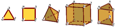
- *npoin, *ndime, *nnode, *nelem, *nmats. They return,
respectively, the number of points, the dimension of the project
being considered, the number of nodes of the
element with the highest number, the number of elements and the number of materials.
All of them are considered as integers and do not carry arguments (see
*format,*intformat), except*nelem, which can bring different types of elements. These elements areOnlyPoints,Linear,Triangle,Quadrilateral,Tetrahedra,Hexahedra,Prism, depending on the number of edges of the element andAll, that comprises all the possible types. The command*nmatsreturns the number of materials effectively assigned to an entity, not all the defined ones. - *GenData. It must carry an argument of integer type that specifies the number
of the field to be printed. This number is the order of the field inside the general data
list. This must be one of the values that are fixed for all the problem,
independently of the interval (see section Problem and intervals data file (.prb)).
The field's name can also be the argument, instead, or even an abbreviation of it.
The arguments
REALorINTto express the type of number for the field are also available (see*format,*intformat,*realformat,*if). If they are not specified, the program will print a character string. It is mandatory to write one of them within an expression, except forstrcmpandstrcasecmp. The numeration must start with number 1. - *IntvData. The only difference with the previous one is that
the field must be one of those fields varying with the interval
(see section Problem and intervals data file (.prb)).
This command must be within a loop over intervals (see
*loop) and the program will automatically update the suitable value for each iteration. - *MatProp. The only difference with the previous ones is that it
must be within a loop over the materials (see
*loop). It returns the property whose field's number or name is defined by its argument. It's recommended the use of names instead of field numbers.
Note: If argument is 0, it returns the material's name.Caution: If there are materials with different number of fields, the user must ensure not to print non-existent fields, using conditionals.
- *ElemsMatProp. The same as Matprop but using the material of the current element.
Must be within a loop over the elements (see
*loop). It returns the property whose field's number or name is defined by its argument. It's recommended the use of names instead of field numbers.
*loop elements
  *elemsnum *elemsmat *elemsmatprop(young)
*end elements
- *Cond. The same previous remarks apply here, although now the user
must notify with the command
*set(see*set) which is the condition being processed. It can be within a loop (see*loop) over the different intervals in case that the conditions vary for each interval. - *ElemsNum: returns the element's number.
*NodesNum: returns the node's number.
*MatNum: returns the material's number.
*ElemsMat: returns the number of the material assigned to the element.
All of this commands must be within a proper loop (see*loop) and change automatically for each iteration. They are considered as integers and cannot carry any argument. The number of materials will be reordered numerically, to begin from number 1 and will increase up to the number of materials assigned to any entity.
-
*LayerNum: returns the layer's number.
*LayerName: returns the layer's name.
*LayerColorRGB: returns the layer's color in RGB (three integer numbers between 0 and 256). If parameter(1),(2)or(3)is specified, the command returns the only the value of one color. RED is 1, GREEN is 2 and BLUE is 3.
Commands *LayerName, *LayerNum and *LayerColorRGB must be inside a loop over layers; you cannot use this commands in a loop over nodes or elements.
Example:*loop layers *LayerName *LayerColorRGB *Operation(LayerColorRGB(1)/255.0) *Operation(LayerColorRGB(2)/255.0) *Operation(LayerColorRGB(3)/255.0) *end layers
-
*NodesLayerNum: returns the layer's number. Must be used in a loop over nodes.
*NodesLayerName: returns the layer's name. Must be used in a loop over nodes.
*ElemsLayerNum: returns the layer's number. Must be used in a loop over elems.
*ElemsLayerName: returns the layer's name. Must be used in a loop over elems.
- *CondNumEntities. The user must have previously
selected a condition (see
*set cond). It returns the number of entities that have a condition assigned over them. - *LayerNumEntities. The user must have previously
selected a layer (see
*set layer). It returns the number of entities that are inside this layer. - *LoopVar. This command must be inside a loop and returns, as an integer, what is
considered to be the internal variable of the loop. This variable takes the value 1 in the
first iteration and increases a unit for each new iteration.
The parameter
elems,nodes,materials,intervals, used as argument for the corresponding loop, allows the program know which one is being processed. Otherwise, if there are nested loops, the program takes the value of the inner loop. - *Operation. It returns the result of an arithmetical expression what should be
written inside parenthesis just immediately behind the command. This operation must be
defined in C-format and can contain any of the commands that return one single value. The
user can force the return of an integer or a real by means of the mentioned parameters
INTorREAL. Otherwise, GiD returns the type according to the result.
The valid C functions that can be used are:
+,-,*,/,(,),=,<,>,!,&,|, numbers and variablessincostanasinacosatanatan2expfabsabspowsqrtstrcmpstrcasecmp
The following are valid examples of operations:*operation(4*elemsnum+1) *operation(8*(loopvar-1)+1)
Note: There cannot be blank spaces between the commands and the parenthesis that include the parameters.Note: Commands inside
*operationdo not need to put * at the beginning. - *LocalAxesNum. It returns the identification name of the local axes system, either when the loop is over the nodes or when it is over the elements, under a referenced condition.
- *nlocalaxes. It returns the number of the defined local axes system.
- *IsQuadratic. It returns the value 1 when the elements are
quadratic or 0 when they are not.
- *Time. It returns the number of seconds elapsed since midnight.
- *Clock. It returns the number of clock ticks (aprox. milliseconds) of elapsed processor time.
EXAMPLE:
*set var t0=clock
*loop nodes
  *nodescoord
*end nodes
*set var t1=clock
ellapsed time=*operation((t1-t0)/1000.0) seconds
- *Units('magnitude'). It returns current unit name for the selected magnitude.
(the current unit is the unit showed inside the unit window)
EXAMPLE
*Units(LENGTH)
- *BasicUnit('magnitude'). It returns basic unit name for the selected magnitude.
(the basic unit is the unit defined as { Basic } in the *.uni file)
EXAMPLE
*BasicUnit(LENGTH)
- *FactorUnit('unit'). It returns the numeric factor to convert a magnitude
from the selected unit to the basic unit.
EXAMPLE
*FactorUnit(PRESSURE)
Multiple values return commands |
These commands return more than one value in a prescribed order, writing them one behind another. All of them, but LocalAxesDef, are able to return one single value when a numerical argument giving the order of the value is added to the command. In this way, these commands can appear within an expression.
LocalAxesDef or the rest of the commands without the numerical argument
cannot be used inside expressions. Following, it is displayed a list of
the commands with the appropriate description:
- *NodesCoord. This command writes the node's coordinates. It must be
inside a loop (see
*loop) over the nodes or elements. The coordinates are considered as real numbers (see*realformatand*format). It will write two or three coordinates according to the problem's dimension (see*Ndime). If*NodesCoordreceives an integer argument (from 1 to 3) inside a loop of nodes, this argument indicates which coordinate x, y or z must be written:
Inside a loop of nodes:
*NodesCoordwrites three or two coordinates depending on the problem's dimension.
*NodesCoord(1)writes the x coordinate of the actual node of the loop.
*NodesCoord(2)writes the y coordinate of the actual node of the loop.
*NodesCoord(3)writes the z coordinate of the actual node of the loop.
If the argumentrealis given, the coordinates will be treated as a real number.
Example: using*NodesCoordinside a loop of nodesCoordinates: Node X Y *set elems(all) *loop nodes *format "%5i%14.5e%14.5e" *NodesNum *NodesCoord(1,real) *NodesCoord(2,real) *end nodes
This command effects a rundown of all the nodes of the mesh, listing their identifiers and coordinates (x and y coordinates).
The contents of theproject_name.datfile could be something like this:Coordinates: Node X Y 1 -1.28571e+001 -1.92931e+000 2 -1.15611e+001 -2.13549e+000 3 -1.26436e+001 -5.44919e-001 4 -1.06161e+001 -1.08545e+000 5 -1.12029e+001 9.22373e-002 ...
*NodesCoordcan also be used inside a loop of elements. In this case, it needs an additional argument that gives the local number of the node inside the element. After this argument it's also possible to give which coordinate has to be written x, y or z.
Inside a loop of elements:
*NodesCoord(4)writes the coordinates of the 4th node of the actual element of the loop.
*NodesCoord(5,1)writes the x coordinate of the 5th node of the actual element of the loop.
*NodesCoord(5,2)writes the y coordinate of the 5th node of the actual element of the loop.
*NodesCoord(5,3)writes the z coordinate of the 5th node of the actual element of the loop.
- *ElemsConec. This command writes the element's connectivities, i.e.,
the list of the nodes that belong to the element, keeping the proper sense for
each case (anti-clockwise sense in 2D and depending on the standards in 3D).
For shells, the user must define the sense. However, this command accepts the
argument
swapand this implies that the ordering of the nodes in quadratic elements will be consecutive instead of hierarchical. The connectivities are considered as integer numbers (see*intformatand*format).If
*ElemsConecreceives an integer argument (begining from 1), this argument indicates which element connectity must be written:*loop elems all conectivities: *elemsconec first conectivity *elemsconec(1) *end elems
Note: In the first versions of GiD, the optional parameter of the last command explained wasinvertinstead of the present (swap). It was changed due to technical reasons. If you have an old.basfile prior to this specification, which contains this command in its previous form, when you try to export the calculation file, you will be warned about this change of use. Be aware that the output file will not be created as the user expects. - *GlobalNodes. This command returns the nodes that belong to an element's face where a condition has been defined (on the loop over the elements).
The sense is the same that the sense of the element's connectivities. The
returned values are considered as integer numbers (see
*intformatand*format).
If*GlobalNodesreceives an integer argument (begining from 1), this argument indicates which face connectity must be written:
So, the local numeration of the faces is:
Triangle:       12  23  31
Quadrilateral:  12  23  34  41
Tetrahedra:     123 243 341 421
Hexahedra:      1234  1485  1562  2673  3784  5876
prism:          123  1452  2563  3641  456
- *LocalNodes. The only difference with the previous one is that the
returned value is the local node's numbering for the corresponding element
(between 1 and
nnode). - *ElemsNnode. This command returns the number of nodes of the current element. (valid only inside a loop over elements)
Note: This command is only available in GiD version 6.2.0b or newer.Example:
*loop elems
  *ElemsNnode
*end elems
- *ElemsNnodeCurt. This command returns the number of vertex nodes of the current element. (valid only inside a loop over elements)
For example, for a quadrilateral of 4, 8 or 9 nodes, it returns the value 4.
Note: This command is only available in GiD version 7.2 or newer. - *ElemsNNodeFace. This command returns the number of face nodes of the current element face. (valid only inside a loop over elements onlyincond, with a previous *set cond of a condition defined over face elements)
Note: This command is only available in GiD version 7.5.2b or newer.Example:
*loop elems
  *ElemsNnodeFace
*end elems
- *ElemsNNodeFaceCurt. This command returns the short (corner nodes only) number of face nodes of the current element face. (valid only inside a loop over elements onlyincond, with a previous *set cond of a condition defined over face elements)
Note: This command is only available in GiD version 7.5.2b or newer.Example:
*loop elems
  *ElemsNnodeFaceCurt
*end elems
- *ElemsType: returns the current element type as a integer value: 1=Linear,2=Triangle,3=Quadrilateral,4=Tetrahedra,5=Hexahedra,6=Prism,7=OnlyPoints. (valid only inside a loop over elements)
Note: This command is only available in GiD version 7.2.2b or newer. - *ElemsTypeName: returns the current element type as a string value: Linear,Triangle,Quadrilateral,Tetrahedra,Hexahedra,Prism,OnlyPoints. (valid only inside a loop over elements)
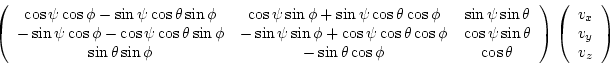
Note: This command is only available in GiD version 7.2.2b or newer. - *LocalAxesDef. This command returns the nine numbers that define the
transformation matrix of a vector from the local axes system to the global one.
Example:
*loop localaxes
*format "%10.4lg %10.4lg %10.4lg"
x'=*LocalAxesDef(1) *LocalAxesDef(4) *LocalAxesDef(7)
*format "%10.4lg %10.4lg %10.4lg"
y'=*LocalAxesDef(2) *LocalAxesDef(5) *LocalAxesDef(8)
*format "%10.4lg %10.4lg %10.4lg"
z'=*LocalAxesDef(3) *LocalAxesDef(6) *LocalAxesDef(9)
*end localaxes
- *LocalAxesDef(EulerAngles). Last command with option
EulerAngles, returns three numbers that are the 3 Euler angles (radians) that define a local axes system.
Rotation of a vector expressed in terms of euler angles
- *LocalAxesDefCenter. This command returns the origin of coordinates of the local axes defined by the user. The "Automatic" local axes do not have a center, so, the point (0,0,0) is returned. The index of the coordinate (from 1 to 3) can optionally be given to
LocalAxesDefCenterto get the x, y or z value.
Example:*LocalAxesDefCenter *LocalAxesDefCenter(1) *LocalAxesDefCenter(2) *LocalAxesDefCenter(3)
Specific commands |
- *\ To avoid line-feeding, the user must write *\, so, the currently
used line continues on the following line of the file
NAME.bas. - *# Written at the beginning of the line, consider this line as a comment and does not write it.
- ** To write an asterisk must be written two asterisks **.
-
*Include. It is possible to include the contents of a slave file inside a master bas with a include command, setting a relative path from the problemtype directory to this secondary file.
Example:
*include includes\execntrlmi.h
Note: The *.bas extension cannot be used for the slave file to avoid multiple output files. -
*MessageBox. This command stops the execution of the
.basfile and prints a message in a window; this command should be used only when a fatal error occurs.
Example:
*MessageBox error: Quadrilateral elements are not permitted.
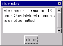
This window appears if the command MessageBox is executed
-
*WarningBox. is the same as
MessageBoxbut without stoping the execution.
Example:
WarningBox Warning: Exist Bad elements. A STL file is a collection of triangles bounding a volume.
The following commands must be written at the beginning of a line and the rest of the line will serve for their modifiers. No additional text should be written.
- *loop, *end, *break. They are declared for the use
of loops. A loop begins with a line that starts with
*loop(no matter the letters case, as for the rest of commands) and contains another word to express the variable of the loop. There are some lines in the middle that will be repeated depending on the values of the variable and whose parameters will keep on changing through the iterations, if necessary. Finally, a loop will end with a line that finishes with*end. After*endthe user may write any kind of comments in the same line. Command *break inside a *loop or *for block, will finish the execution of the loop and will continue after the *end line.The variables that are available for
*loopare the following:- elems, nodes, materials, layers, intervals, localaxes. They mean, respectively, that the loop will iterate over the elements, nodes, materials, layers, intervals or local axes systems. The loops can be nested among them. The loop over the materials will iterate only over the effectively assigned materials to an entity, in spite of the fact that more materials had been defined. The number of the materials will begin with number 1. If a command that depends on the loop is located outside it, the number also will take, by default, the value 1.
It's possible to make a loop over the materials defined, but not used with the modifier *NotUsed
Example:*loop materials *NotUsed
After the command*loop, if the variable iselemsornodes, the user may include a modifier*all,*OnlyInCondor*OnlyInLayer. The first one signifies that the iteration is going to be performed over all the entities; the*OnlyInCondmodifier implies that the iteration will only take place over the entities that accomplish the concerned condition. This condition must have been previously defined with*set cond.*OnlyInLayerimplies that the iteration will only take place over the entities that are in the specified layer; layers must be specified with the command*set Layer. By default, it is assumed that the iteration will affect all the entities.
Example 1:*set elems(all) *loop nodes *format "%5i%14.5e%14.5e" *NodesNum *NodesCoord(1,real) *NodesCoord(2,real) *end nodes
This command effects a rundown of all the nodes of the mesh, listing their identifiers and coordinates (x and y coordinates).
Example 2:*Set Cond Point-Weight *nodes *loop nodes *OnlyInCond *NodesNum *cond(1) *end
This effects a rundown of all the nodes assigned the condition "Point-Weight" and provides a list of their identifiers and the first "weight" field of the condition in each case.
Example 3:*Loop Elems *ElemsNum *ElemsLayerNum *End Elems
This effects a rundown of all the elements and provides a list of their identifier and the identifier of the layer to which they belong.
Example 4:*Loop Layers *LayerNum *LayerName *End Layers
This effects a rundown of all the layers and for each layer it lists its identifier and its name. - *if, *else, *elseif, *endif. These commands
create the conditionals.
The format is a line which begins with
*iffollowed by an expression between parenthesis. This expression will be written in C-language syntax, value return commands, will not begin with*and its variables must be defined as integers or reals (see*format,*intformat,*realformat), with the only exception ofstrcmpandstrcasecmp. It can include relational as well as arithmetic operators inside the expressions.The following are valid examples of the use of the conditionals:
*if((fabs(loopvar)/4)<1.e+2)
*if((p3<p2)||p4)
*if((strcasecmp(cond(1),"XLoad")==0)&&(cond(2)!=0))
The first example is a numerical example where the condition is accomplished for the values of the loop under 400, while the other two are logical operators where the condition is accomplished whenp3<p2orp4is different from 0 in the first case and when the first field of the condition is calledXLoad(with this particular writing) and the second is not null in the second case.If the checked condition is true, GiD will write all the lines until finding the corresponding
*else,*elseifor*endif(*endis equivalent to*endifafter*if).*elseor*elseifare optional and require the writing of all the lines until the corresponding*endif, but only when the condition given by*ifis false. If*elseor*elseifexist, it must be written between*ifand*endif. The conditionals can be nested among them.The behaviour of
*elseifis identical to the behaviour of*elsewith the addition of a new condition:*if(GenData(31,int)==1) ...(1) *elseif(GenData(31,int)==2) ...(2) *else ...(3) *endif
In the previous example, the body of the first condition (written as1) will be written into the data file ifGenData(31,int)is 1, the body of the second condition (written as2) will be written into the data file ifGenData(31,int)is 2 and if none of both is true, the body of the third condition (written as3) will be written into the data file.Note: A conditional can also be written in the middle of a line. To do this, the user will begin another line to write the conditional by means of the command *\.
- *for, *end, *break. The syntax of this command is equivalent
to
*forin C-language.*for(varname=expr.1;varname<=expr.2;varname=varname+1) *end for
The meaning of this statement is the execution of a controlled loop, sincevarnameis equal toexpr.1until it is equal toexpr.2, with an incremental value of 1 for each step.varnameis any name andexpr.1andexpr.2are arithmetical expressions or numbers whose only restrictions are to express the range of the loop. Command *break inside a *loop or *for block, will finish the execution of the loop and will continue after the *end line.*for(i=1;i<=5;i=i+1) variable i=*i *end for
- *set. This command has the following purposes:
*set cond.To set a condition.*set Layer "layer name" *elems|nodes.To set a layer.*set elems.To indicate the elements.*set var.To indicate the variables to use.
*Setwill also be valid in all the examples.*set cond.: In the case of the conditions, GiD allows the combination of a group of them via the use of
*add cond.When a specific condition is about to be used, it must be defined first and afterwards, this will be used until the definition of another one. If this feature is performed inside a loop over intervals, the corresponding entities will be chosen. Otherwise, the entities will be those referred to the first interval.
This is done in this way because when the user indicates to the program that a condition is going to be used, GiD creates a table that allows to know the number of entities over which this condition has been applied. It is necessary to specify if the condition takes place over the *nodes, over the *elems or over *layers to create the table.So, a first example to check the nodes where there displacement constraints exist can be:
*Set Cond Volu-Cstrt *nodes
*Add Cond Surf-Cstrt *nodes
*Add Cond Line-Cstrt *nodes
*Add Cond Poin-Cstrt *nodes
that allows the user to apply the conditions directly over any geometric entity.*Set Layer "layer name" *elems|nodes
*Add Layer "layer name"
*Remove Layer "layer name"
This command set a group of nodes. In the following loops over nodes/elements with the modifier*OnlyInLayerthe iterations will only take place over the nodes/elements of that group.
Example 1:*set Layer example_layer_1 *elems *loop elems *OnlyInLayer N�:*ElemsNum Name of Layer:*ElemsLayerName N� of Layer :*ElemsLayerNum *end elems
Example 2:*loop layers *set Layer *LayerName *elems *loop elems *OnlyInLayer N�:*ElemsNum Name of Layer:*ElemsLayerName N� of Layer :*ElemsLayerNum *end elems *end layersIn this example the command*LayerNameis used to get the layer name.
There are some modifiers available to point out particular specifications on the conditions.If command
*CanRepeatis added after*nodesor*elemsin*Set cond, one entity can be several times in the entities list. If command*NoCanRepeatis used, entities will be just once in the entities list. By default,*CanRepeatis off except for the case of one condition that have the*CanRepeatflag already set.A typical case not to use
*CanRepeatwould be:*Set Cond Line-Constraints *nodes
In this case, when two lines share one endpoint, instead of two nodes in the list, only one is written.A typical case to use
*CanRepeatwould be:*Set Cond Line-Pressure *elems *CanRepeat
in this case, if one triangle of quadrilateral has more than one face in the marked boundary, we want this element to appear several times in the elements list, one for each face.Other modifiers are used to inform the program that there are nodes or elements that can satisfy one condition more than once (for instance, a node that belongs to a certain number of lines with different prescribed movements) and that have to appear unrepeated in the data input file, or, in the opposite case, that have to appear only if they satisfy more than one condition. These requirements are achieved with the commands
*or(i,type)and*and(i,type), respectively, after the input of the condition, whereiis the number of the condition to be considered andtypeis the type of the variable (integer or real).For the previous example there can be nodes or elements in the intersection of two lines or maybe belonging to different entities where the same condition had been applied. To avoid the repetition of these nodes or elements, GiD has the modifier
*or, and in the case that two or more different values were applied over a node or element, GiD only would consider one, being this value different from zero. The reason for that can be easily understood looking at the following example. Considering the previous commands transformed as:*Set Cond Volu-Cstrt *nodes *or(1,int) *or(2,int) *Add Cond Surf-Cstrt *nodes *or(1,int) *or(2,int) *Add Cond Line-Cstrt *nodes *or(1,int) *or(2,int) *Add Cond Poin-Cstrt *nodes *or(1,int) *or(2,int)
where*or(1,int)means the assignment of that node to the considered ones satisfying the condition if the integer value of the first condition's field is different from zero (*or(2,int)means the same assignment if the integer value of the second condition's field is different from zero). Let us imagine that a zero in the first field implies a restricted movement in the direction of the X-axis and a zero in the second field implies a restricted movement in the direction of the Y-axis. If a point belongs at the same time to an entity whose movement in the direction of the X-axis is constrained, whereas its movement in the direction of the Y-axis is released and to an entity whose movement in the direction of the Y-axis is constrained, whereas its movement in the direction of the X-axis is released, GiD would join both conditions in that point, appearing as a fixed point in both directions and as a node satisfying the four expressed conditions would be counted only once.The same considerations explained for adding conditions through the use of
*add condapply to the elements with the only change of putting*add elems.Moreover, sometimes it can be of interest to remove sets of elements from the assigned ones to the specific conditions. This can be done with the command*remove elems.So, for instance, GiD allows combinations of the type:*Set Cond Dummy *elems *Set elems(All) *Remove elems(Linear)
to indicate that all dummy elements apart from the linear ones will be considered, as well as:*Set Cond Dummy *elems *Set elems(Hexahedra) *Add elems(Tetrahedra) *Add elems(Quadrilateral) *Add elems(Triangle)
The format for*set vardiffers from the syntax for the other two*setcommands. Its syntax is as follows:*Set var varname = expression
wherevarnameis any name andexpressionis any arithmetical expression, number or command, having the latter to be written without * and having to be defined asIntorReal.
Can also call atclprocedure, but it must return a numeric result.The following are valid examples for these assignments:
*Set var ko1=cond(1,real) *Set var ko2=2 *Set var S1=CondNumEntities *Set var p1=elemsnum() *Set var b=operation(p1*2) *tcl(proc MultiplyByTwo { x } { return [expr {$x*2}] })*\ *Set var a=tcl(MultiplyByTwo *p1) - *intformat, *realformat,*format. These commands explain
how the output of different mathematical expressions will be written into the
analysis file. The use of this command consist in a line which begins with
the corresponding version,
*intformat,*realformator*format, (independently of the use of capital letters) and continues with the desired writing format, expressed in C-language syntax argument, between double quotes (").The integer definition of
*intformatand the real of*realformatremain unchanged until another definition via*intformatand*realformat, respectively, is provided. The argument of these two commands is composed by an unique field. This is the reason why the*intformatand*realformatcommands are usually invoked at the initial stages of the.basfile, to set the format configuration of the integer or real numbers to be output during the rest of the process.The
*formatcommand can include several fields definitions in its argument, mixing integer and real definitions, but it will only affect the line that follows the command's instance one. Hence, the*formatcommand is typically used when outputting a listing, to set a temporary configuration.In the next paragraphs, there is an explanation of the C format specification, refered to the fields specification to be included into the argument of these commands. Keep in mind that the type of argument that the
*formatcommand expects may be composed by several fields, and the*intformatand*realformatcommands' arguments are composed by an unique field, declared as integer and real, respectively, all inside double quotes:A format specification, which consist of optional and required fields, has the following form:
%[flags][width][.precision]type
The start of a field is signaled by the percentage symbol (%). for Each field specification is composed by some flags, the minimum width, a separator point, the precision of the field and a letter which specifies the type of the data to be represented. The type field is the only one required.The most common flags are:
- To left align the result
+ To prefix the numeric output with a sign (+ or -)
# To force the real output value to contain a decimal point.
The most usual representations are integers and floats. For the integers there are available thedandiletters, that force to read the data as signed decimal integer andufor unsigned decimal integer.For floating point representation, there are the
e,fandgletters, being used then a decimal point to separate the minimum width of the number and the precision. The number of digits after the decimal point depends on the requested precision.
Note: The standard width specification never causes a value to be truncated. It exists in GiD a special command:*SetFormatForceWidth, to enable this truncation to a prescribed number of digits.For string representation, must be used the
sletter. Characters are printed until the precision value is reached.The following are valid examples of the use of format:
*Intformat "%5i"
With this sentence, usually located on the start of the file, the output of an integer quantity is forced to be right aligned on the fifth column of the text format on the right side. If the number of digits exceeds five, the representation of the number is not truncated.*Realformat "%10.3e"
This sentence, that also is located frequently at the first lines of the template file, sets the output format for the real numbers as exponential with minimum ten digits, and three digits after the decimal point.*format "%10i%10.3e%10i%15.6e"
This complex command will specify a multiple assignment of formats to some output columns. These columns are generated with the line command that will follow the format line. The subsequent lines will not use this format, and will follow the general settings of the template file or the general formats: *IntFormat, *RealFormat. - *SetFormatForceWidth, *SetFormatStandard
The default width specification of a "C/C+" format, never causes a value to be truncated.
*SetFormatForceWidthis a special sentence to allows the truncation if the number of characters to print exceeds the specified width.
*SetFormatStandardchanges to the default state, with truncation disabled.
For example:*SetFormatForceWidth *set var num=-31415.16789 *format "%8.3f" *num *SetFormatStandard *format "%8.3f" *num
Output:-31415.1 -31415.168
The first number is truncated to 8 digits, but the second number, printed with "C" standard, have 3 decimals, but more than 8 digits. - *Tcl
This command permits to print information using the Tcl extension
language. The argument of this command must be a valid Tcl command or
expression that must return the string that will be printed. Typically,
the Tcl command is defined in the Tcl file (.tcl). (see see section TCL/TK EXTENSION for details).
Example: in this example the *tcl command is used to call a tcl function defined in the problem's type .tcl file. That function can receive a variable value as argument with *variable. Also it is possible to assign the returned value to a variable, but the tcl procedure must return a numeric value.
In the .bas file:*set var num=1 *tcl(WriteSurfaceInfo *num) *set var num2=tcl(MultiplyByTwo *num)
In the .tcl file:proc WriteSurfaceInfo { num } { return [GiD_Info list_entities surfaces $num] } proc MultiplyByTwo { x } { return [expr {$x*2}] }
Detailed example - Template file creation |
Next is an example of template file creation, step by step:
Note that this is a concrete file for a particular solver, so it's a sure state that some or all of the commands that this solver program expects, will be non standard or incompatible with the one that another user owns.
In this example, this particular solver treats a line like a comment,
inside the calculation input file, if its prefix is a $ sign. In
your case, it can be another convention.
Anyway, the actual target of this example is the comprehension of the commands that GiD exposes to the user. This is the universal method to access to GiD's internal database, and then output the desired data to the solver.
Also, it's assumed that the user will create the file or files with .bas
extension, inside the working directory where the problem type file is
located. The name must be
problem_type_name.bas for the first file and any other name
for the additional .bas files. Each .bas file will be read by GiD, and translated to a .dat file.
It is very important to remark that any word in the .bas file
having no meaning as a GiD compilation command or not belonging to any
command instructions (parameters), will be verbatim written to the output file.
First, we create the header that the solver, on this particular case, needs.
This is the name of the solver application and a brief description of its behaviour.
$-----------------------------------------------------
CALSEF: PROGRAM FOR STRUCTURAL ANALYSIS
Then, another particular sentence that may be incompatible in your case,
although a similar one may exist for your solver. It's a commented line
with the ECHO ON command. This line, when uncommented, is useful
if you want to monitor the progress of the calculation.
$-----------------------------------------------------
$ECHO ON
The next line specifies the type of calculation and the materials involved on the calculation, and it's not a GiD related command either.
$-----------------------------------------------------
ESTATICO-LINEAL, EN SOLIDOS
As you can see, it's used a commented line with dashes to separate the different parts of the file improving the readability of the text.
Here comes the initialization of some variables. This is needed by the solver to start the calculating process.
The following assignments take the first (parameter (1))
and second (parameter (2)) fields in the general problem,
as the number of problems and the title of the problem.
The actual position of a field is determined checking its order on the problem file, so you will guess this is a method that depends on a strict position.
Assignment of the first (1) Field of the Problem data file, with
the command *GenData(1):
$-----------------------------------------------------
$NUMBER OF PROBLEMS:
NPROB = *GenData(1)
$-----------------------------------------------------
Assignment of the second (2) field assignment, *GenData(2):
$ TITLE OF THE PROBLEM:
TITULO= *GenData(2)
$-----------------------------------------------------
The next instruction takes the field where the starting time is saved.
On this case, it is on the 10th position of the general problem data
file, but we will use another feature of the *GenData command,
the parameter of the command will be the name of the field.
This is a preferable method, because if the list is shifted due to the adding or subtracting of a field, you will not loose the actual position. This command accepts an abbreviation, if there is no conflict with other field name.
$-----------------------------------------------------
$ TIME OF START:
TIME= *GenData(Starting_time)
$-----------------------------------------------------
Here comes the init of some general variables refering to the project we are considering, as the number of points, the number of elements or the number of materials.
The first line is a description of the section.
$ DIMENSIONS OF THE PROBLEM:
Then it is a line that introduces the next assignments
DIMENSIONS :
Which is followed by another one with the three assignments of variables.
NPNOD gets, from the *npoin function, the number of nodes of
the model; NELEM gets, from *nelem, or the total number of
elements of the model or the number of elements of every kind of element
and nmats is initialized with the number of materials:
NPNOD= *npoin, NELEM= *nelem, NMATS= *nmats, \
Then comes a line where NNODE gets the maximum number of nodes per
element and NDIME gets the variable *ndime. This variable must
be a number that specifies if all the nodes are on the plane whose
Z values are equal to 0 (NDIME=2) or if they are not (NDIME=3):
NNODE= *nnode, NDIME= *ndime, \
The next lines take data from the general data fields in the problem file.
NCARG gets the number of charge cases;
NGDLN the number of degrees of freedom;
NPROP the properties number;
NGAUSS the gauss number;
NTIPO, is assigned dynamically:
NLOAD= *GenData(Load_Cases), *\
You could use NGDLN= *GenData(Degrees_Freedom), *\, but because
the length of the argument will make exceed a line, we have abbreviated
its parameter (there is no conflict with other question name in
this problem file), to simplify the command.
NGDLN= *GenData(Degrees_Fre), *\
NPROP= *GenData(Properties_Nbr), \
NGAUS= *GenData(Gauss_Nbr) , NTIPO= *\
Note that the last assignment is ended with the specific command
*\, to avoid the line feeding. This permits to include a
conditional assignment of this variable, depending
on the data in the General data problem.
Inside the conditional it is used a C format like
strcmp instruction. This instruction compares the two strings passed
as parameter, and returns an integer number which express the relationship
between the two strings. If the result of the
operation is equal to 0, the two strings are identical;
if it is a positive integer, the first argument is greater than the second,
and otherwise, the second argument string is less.
The script checks what problem type is
declared in the general data file, and then it assigns the coded
number for the this type to the NTIPO variable:
*if(strcmp(GenData(Problem_Type),"Plane-stress")==0)
1 *\
*elseif(strcmp(GenData(Problem_Type),"Plane-strain")==0)
2 *\
*elseif(strcmp(GenData(Problem_Type),"Revol-Solid")==0)
3 *\
*elseif(strcmp(GenData(Problem_Type),"Solid")==0)
4 *\
*elseif(strcmp(GenData(Problem_Type),"Plates")==0)
5 *\
*elseif(strcmp(GenData(Problem_Type),"Revol-Shell")==0)
6 *\
*endif
You have to cover all the cases within the if sentences,
or end the commands with an else, if you don't want unpredictable
results, like the next line raised to the place where the parameter will
have to be:
$ Default Value:
*else
0*\
*endif
Although in our case this last rule has not been followed, it could be a very good option, when the problem file has been modified or created by another user, and the new specification may differ from the one we expect.
The next assignment is formed by a string compare conditional, to inform the solver about a setting of the configuration.
First is the output of the variable to be assigned.
, IWRIT= *\
Then there is a conditional where it's compared the string contained
on the value of the Result_File field with the string "Yes". If the
result is 0, then the two strings are the same,
and we output an 1, to declare a boolean TRUE.
*if(strcmp(GenData(Result_File),"Yes")==0)
1 ,\
Then we compare the same value string with the string "No", to check the
complementary option. If we find that the strings match, then we output
a 0.
*elseif(strcmp(GenData(Result_File),"No")==0)
0 ,\
*endif
The second last assignment is a simple output of the solver field contents into the INDSO variable:
INDSO= *GenData(Solver) , *\
The last assign is a little more complicated. It requires the creation of
some internal values, with the aid of the command *set cond.
The first action to execute is to set the conditions, so we can access its parameters. This setting may serve for several loops or instructions, as long as the parameters needed for the other blocks of instructions are the same.
This line sets the condition Point-Constraints as an active condition.
The *nodes modifier means that the condition will be listed over nodes.
The *or(... modifiers are necessary when an entity shares
some conditions, because it belongs to two or more elements.
As an example, take a node which is part of two lines, and each
of these lines have assigned a different condition. This node, a common
point of the two lines, will have this two conditions into
its list of properties. So declaring the *or
modifiers, GiD will decide which condition to use, between the list
of conditions of the entity.
A first instruction will be this, where the parameters of the *or
commands are an integer number ((1, and (3,, respectively on
this example) and the specification int, that forces
GiD to read the condition whose number position is the integer number.
In our case, we find that the first (1) field
of the condition file is X-constraint, and the third (3),
is Y-constraint:
Gid still has no support for the substitution of the position of the condition in the file by its corresponding label, as succeeds in the case of the fields of the problem data file.
*Set Cond Surface-Constraints *nodes *or(1,int) *or(3,int)
Now we want to complete the setting of the loop, with the addition of new conditions.
*Add Cond Line-Constraints *nodes *or(1,int) *or(3,int)
*Add Cond Point-Constraints *nodes *or(1,int) *or(3,int)
Observe the order in which the conditions have been included: first the
surface constraints with the *Set Cond command, since it is the
initial sentence. Then the pair of *Add Cond sentences, the
line constraints and as the last one, the point constraints sentence.
This logical hierarchy forces the points as the most important items, due
to the fact that the program takes
Finally, we set a variable with the number of entities assigned to this particular condition.
Note that the execution of this instruction is only possible if a condition has been set previously.
NPRES= *CondNumEntities
To end this section, we put a separator on the output file:
$-----------------------------------------------------
Thus, after the init of those variables, this part of the file ends up as:
$ DIMENSIONS OF THE PROBLEM:
DIMENSIONES :
 NPNOD= *npoin,  NELEM= *nelem,  NMATS= *nmats,     \
 NNODE= *nnode,  NDIME= *ndime,                     \
 NCARG= *GenData(Charge_Cases), *\
 NGDLN= *GenData(Degrees_Fre), *\
 NPROP= *GenData(Properties_Nbr), \
 NGAUS= *GenData(Gauss_Nbr) , NTIPO= *\
*if(strcmp(GenData(Problem_Type),"Tens-Plana")==0)
1 *\
*elseif(strcmp(GenData(Problem_Type),"Def-Plana")==0)
2 *\
*elseif(strcmp(GenData(Problem_Type),"Sol-Revol")==0)
3 *\
*elseif(strcmp(GenData(Problem_Type),"Sol-Tridim")==0)
4 *\
*elseif(strcmp(GenData(Problem_Type),"Placas")==0)
5 *\
*elseif(strcmp(GenData(Problem_Type),"Laminas-Rev")==0)
6 *\
*endif
, IWRIT= *\
*if(strcmp(GenData(Result_File),"Yes")==0)
1 ,\
*elseif(strcmp(GenData(Result_File),"No")==0)
0 ,\
*endif
   INDSO= *GenData(Solver) , *\
*Set Cond Surface-Constraints *nodes *or(1,int) *or(3,int)
*Add Cond Line-Constraints *nodes *or(1,int) *or(3,int)
*Add Cond Point-Constraints *nodes *or(1,int) *or(3,int)
NPRES=*CondNumEntities
$-----------------------------------------------------
After creation or reading of our model, once generated the mesh
and applied the conditions, we can export the file (file project_name.dat) and send it to the solver.
The command to create the .dat file can be found on the
File / Export / Calculation File
GiD menu. It's also possible to use the keyboard shortcut Control-x Control-c
This would be the contents of the project_name.dat file:
$-----------------------------------------------------
CALSEF: PROGRAM FOR STRUCTURAL ANALYSIS
$-----------------------------------------------------
$ECHO ON
$-----------------------------------------------------
LINEAR-STATIC, SOLIDS
$-----------------------------------------------------
$NUMBER OF PROBLEMS:
NPROB = 1
$-----------------------------------------------------
$ PROBLEM TITLE
TITLE= Title_name
$-----------------------------------------------------
$DIMENSIONS OF THE PROBLEM
DIMENSIONS :
  NPNOD=    116 ,  NELEM= 176 ,   NMATS=  0 ,     \
  NNODE=      3 ,  NDIME=   2 ,                   \
  NCARG=      1 ,  NGDLN=   1 ,   NPROP=  5 ,     \
  NGAUS=      1 ,  NTIPO=   1 ,   IWRIT=  1 ,     \
  INDSO=     10 ,  NPRES=   0
$-----------------------------------------------------
Here begins the calculation input, the actual starting of data transfer
A) Elements, materials and connectivities listing |
Now we want to output the desired results to the output file.
This first line, apparently a title or label, is the way that
offers the solver, in this example, to determine the
beginning and end of a loop section. This
block of instructions ends with the next END_GEOMETRY sentence,
also for this example.
GEOMETRY
Here, we introduce an user informative couple of lines.
A title of the first subsection, ELEMENTAL CONNECTIVITIES:
$ ELEMENTAL CONNECTIVITIES
And here is the header that precedes the output list, a user oriented data:
$ ELEM. MATER. CONNECTIVITIES
And then we travel trough the elements of the model, by the action of the
*loop instruction, followed in this case by the elems argument.
*loop elems
For each element in the model, GiD will output:
its element number, by the action of the *elemsnum command,
the material assigned to this element, using the *elemsmat command,
and the connectivities associated to the element, with the command
*elemsConec:
  *elemsnum *elemsmat *elemsConec
*end elems
You can use the parameter swap if you are working with quadratic
elements and the listing modes of the nodes is non hierarchical
(by default first list corner nodes, and after mid nodes).
  *elemsnum *elemsmat *elemsConec(swap)
*end elems
Here finishes the first part of this section.
B) Formatted nodes and coordinates listing |
And here starts the next section NODAL COORDINATES:
$ NODAL COORDINATES
Next is the header of the output list:
$ NODE COORD.-X COORD.-Y COORD.-Z
Now GiD will trace all the nodes of the model:
*loop nodes
For each node in the model, it will generate the output of the number of
node, *NodesNum and the coordinates for this node *NodesCoord.
The command executed before the output, *format, will force that the
resulting output follow the guidelines of formatting specified.
On this case, the *format command gets a string parameter with a set
of codes:
%6i, which specify that the first word in the list is coded as a integer and
is printed six points from the left, the rest of the three codes,
%15.5f, are ordering the printing of a real number, represented on
a floating point format, with a distance of 15 spaces between columns
(the number will be shifted to have the last digit in the 15th position of
the column) and the fractional part of the number will be represented with
five digits.
Note that this is the C language format command.
*format "%6i%15.5f%15.5f%15.5f"
  *NodesNum *NodesCoord
*end
And at the end of the section, it's the finishing mark sentence, in this solver example.
END_GEOMETRY
The full set of commands to make this part of the output is showed the next lines.
GEOMETRY
$ ELEMENT CONNECTIVITIES
$ ELEM. MATER.    CONNECTIVITIES
*loop elems
  *elemsnum *elemsmat *elemsConec
*end elems
$ NODAL COORDINATES
$  NODE  COORD.-X   COORD.-Y   COORD.-Z
*loop nodes
*format "%6i%15.5f%15.5f%15.5f"
  *NodesNum *NodesCoord
*end
END_GEOMETRY
The result of the compilation, output to a file (project_name.dat) to be processed by the
solver program.
The first part of the section:
$-----------------------------------------------------
GEOMETRY
$ ELEMENT CONNECTIVITIES
$ ELEM. MATER.    CONNECTIVITIES
     1      1     73    89    83
     2      1     39    57    52
     3      1     17    27    26
     4      5      1     3     5
     5      5      3    10     8
     6      2     57    73    67
     .      .      .     .     .
     .      .      .     .     .
     .      .      .     .     .
   176      5     41    38    24
And the second part of the section:
$ NODAL COORDINATES
$  NODE  COORD.-X   COORD.-Y   COORD.-Z
       1         5.55102        5.51020
       2         5.55102        5.51020
       3         4.60204        5.82993
       4         4.60204        5.82993
       5         4.88435        4.73016
       6         4.88435        4.73016
       .         .              .
       .         .              .
       .         .              .
     116        -5.11565        3.79592
END_GEOMETRY
If the solver module you are using needs a list of the nodes that have assigned a condition, like for example, a neighborhood condition, you have to provide it as is explained in the next example:
C) Nodes listing declaration |
First, we set the necessary conditions, as it was done in the previous section.
*Set Cond Surface-Constraints *nodes *or(1,int) *or(3,int)
*Add Cond Line-Constraints *nodes *or(1,int) *or(3,int)
*Add Cond Point-Constraints *nodes *or(1,int) *or(3,int)
NPRES=*CondNumEntities
After the data init and declarations, the solver requires a list of nodes, with boundary conditions and the fields that have been assigned
In this example, all the selected nodes will be output, also printing the 3 conditions. The columns will be output with no aparent format:
First, there is a line with the header of the section for the solver program and a commentary line for the user
BOUNDARY CONDITIONS
$ RESTRICTED NODES
Then comes the first line of the output list, the header:
$ NODE CODE PRESCRIPTED VALUES
Then the loop instruction, over nodes, and with the specification
argument *OnlyInCond, to iterate only over the entities that have
the condition assigned. This is the condition that has been set on
the previous lines.
*loop nodes *OnlyInCond
The next line is the format command, followed by the lines
with the commands to fill the fields of the list.
*format "%5i%1i%1i%f%f"
   *NodesNum *cond(1,int) *cond(3,int)  *\
Also into the *format command influence there are the next couple
of if sentences. If the degrees of freedom field contains an
integer equal or greater than 3, the number of properties will be
output.
*if(GenData(Degrees_Freedom_Nodes,int)>=3)
*cond(5,int) *\
*endif
And if the value of the same field is equal to 5 the output will be
a pair of zeros.
*if(GenData(Degrees_Free,int)==5)
0 0  *\
*endif
The next line ouputs the values contained in the second and fourth fields, both real numbers.
*cond(2,real) *cond(4,real) *\
In a similar manner as done in the previous if sentences here come
a group of lines to output the sixth condition field value, if the number
of degrees of freedom is equal or greater than three, and output a pair of
zeros if it's equal to five.
*if(GenData(Degrees_Free,int)>=3)
*cond(6,real) *\
*endif
*if(GenData(Degrees_Free,int)==5)
0.0 0.0  *\
*endif
Finally, to end the section, the *end command closes the previous
*loop. The last line is the label of the end of the section.
*end
END_BOUNDARY CONDITIONS
$-------------------------------------------------------
The full set of commands included in this section are the next:
BOUNDARY CONDITIONS
$ RESTRICTED NODES
$ NODE CODE         PRESCRIPTED VALUES
*loop nodes *OnlyInCond
*format "%5i%1i%1i%f%f"
   *NodesNum *cond(1,int) *cond(3,int)  *\
*if(GenData(Degrees_Free,int)>=3)
*cond(5,int) *\
*endif
*if(GenData(Degrees_Free,int)==5)
0 0  *\
*endif
*cond(2,real) *cond(4,real) *\
*if(GenData(Degrees_Free,int)>=3)
*cond(6,real) *\
*endif
*if(GenData(Degrees_Free,int)==5)
0.0 0.0  *\
*endif
*end
END_BOUNDARY CONDITIONS
$-----------------------------------------------------
If it is needed the output of a list of the materials
D) Materials listing declaration |
As a must, the first lines are the title of the section and a commentary.
MATERIAL PROPERTIES
$ MATERIAL PROPERTIES FOR MULTILAMINATE
Then there is the loop sentence, this time related to materials.
*loop materials
Then comes the line were the number of the material and its different properties are output.
*matnum() *MatProp(1) *MatProp(2) *MatProp(3) *MatProp(4)
Finally comes the ending of the section.
*end
END_MATERIAL PROPERTIES
$-----------------------------------------------------
The full set of commands is the next:
MATERIAL PROPERTIES
$ MATERIAL PROPERTIES FOR MULTILAMINATE
*loop materials
   *matnum() *MatProp(1) *MatProp(2) *MatProp(3) *MatProp(4)
*end
END_MATERIAL PROPERTIES
$-----------------------------------------------------
If it is needed the output of a list of the elements
E) Elements listing declaration |
First, we set the loop to the interval of the data.
*loop intervals
The next couple of lines indicate the starting of one section and the title of the example, taken from the first field in the interval data with an abbreviation on the label. They are followed by a comment explaining the type of data we are using.
LOADS
    TITLE: *IntvData(Charge_case)
$ LOAD TYPE
First, we set the condition as done before. If one condition is assigned
twice or more to the same element, without the include of the
*CanRepeat parameter in the *Set Cond the condition will
appear once, if exists the *CanRepeat parameter,
then the number of conditions that will appear is the number of times is
the number of times it was assigned to the condition.
*Set Cond Face-Load *elems *CanRepeat
Then, a condition checks if exist any element into the condition.
*if(CondNumEntities(int)>0)
Next is a title of the next section, followed by a comment for the user.
DISTRIBUTED ON FACES
$ LOADS DISTRIBUTED ON ELEMENT FACES
We assign the number of nodes to a variable.
$ NUMBER OF NODES BY FACE
NODGE =  2
$ LOADED FACES AND FORCE VALUES
*loop elems *OnlyInCond
      ELEMENT=*elemsnum(), CONNECTIV *globalnodes
      *cond(1) *cond(1)  *cond(2) *cond(2)
*end
END_DISTRIBUTED ON FACES
*endif
Finally, output of a list of the nodes and conditions
F) Nodes and its conditions listing declaration |
As ever, the first thing to do in the setting of the conditions.
*Set Cond Point-Load *nodes
As in the previous section, the next loop will be executed only if exists any condition in the selection.
*if(CondNumEntities(int)>0)
Here starts the loop over the nodes.
PUNCTUAL ON NODES
*loop nodes *OnlyInCond
      *NodesNum *cond(1) *cond(2) *\
The next *if sentences, condition the output writting of
the end of the line.
*if(GenData(Degrees_Free,int)>=3)
*cond(3) *\
*endif
*if(GenData(Degrees_Free,int)==5)
0 0  *\
*endif
*end
To end the section, here comes the label and the if closing.
END_PUNCTUAL ON NODES
*endif
Finally, it is written an information label, if the value of
the second field in the interval data section, inside the problem file, is
equal to "si" (yes).
*if(strcasecmp(IntvData(2),"Si")==0)
SELF_WEIGHT
*endif
After the end of this loop, it comes the label that identifies the end of
the forces section, but the actual end of the section will be the next
*end command, located some lines after.
END_LOADS
Before the end of the section, nevertheless, we indicate the solver which
will be the postprocess file. This information is gathered from the
*IntvData command. The argument that this command receives (3)
specifies that the name of the file is in the third field of the loop
iteration of the interval.
$-----------------------------------------------------
$POSTPROCESS FILE
FEMV = *IntvData(3)
To end the forces interval loop, finally comes the *end
command:
$-----------------------------------------------------
*end
Finally, the file is ended with the sentence required by the solver:
END_CALSEF
$-----------------------------------------------------
The preceding section is compiled complete into the following lines:
*Set Cond Point-Load *nodes
*if(CondNumEntities(int)>0)
PUNCTUAL ON NODES
*loop nodes *OnlyInCond
      *NodesNum *cond(1) *cond(2) *\
*if(GenData(Degrees_Free,int)>=3)
*cond(3) *\
*endif
*if(GenData(Degrees_Free,int)==5)
0 0  *\
*endif
*end
END_PUNCTUAL ON NODES
*endif
*if(strcasecmp(IntvData(2),"Si")==0)
SELF_WEIGHT
*endif
END_LOADS
$-----------------------------------------------------
$POSTPROCESS FILE
FEMV = *IntvData(3)
$-----------------------------------------------------
*end
END_CALSEF
$-----------------------------------------------------
With this section ends the template file example.
Executing an external program |
Once all the files of the problem type are finished (.cnd, .mat, .prb, .sim, .bas files), you are able to run the solver. It may be interesting to run it directly from inside GiD.
To do so, it is necessary to create the file problem_type_name.bat in the problem type directory.
This must be a shell script that can contain any type of information and that will
be different for every operating system. When the user selects the option CALCULATE in the GiD preprocess this shell script is executed. (see section CALCULATE)
Because the .bat file will be different depending on the operating system, it's possible to create two files: one for Windows and another for Unix/Linux.
The Windows file has to be named as: problem_type_name.win.bat.
The Unix/Linux file has to be named as: problem_type_name.unix.bat.
If GiD founds a .win.bat or .unix.bat file, the file problem_type_name.bat will be ignored.
If a .bat file exists in the problem type directory, when choosing Start in the calculations window, GiD will automatically write the analysis file inside the example directory assigning
the name project_name.dat to this file (if more files, names project_name-1.dat ...
are used). Next, this shell script will be executed. GiD will assign to this script 3
arguments:
- 1st argument:
project_name(name of the current project) - 2nd argument:
c:\a\b\c\project_name.gid(path of the current project) - 3rd argument:
c:\a\b\c\problem_type_name.gid(path of the problem type selected)
Among other utilities, this script can move or rename files and execute the process until it finishes.
Note1: This file must have the executable flag set (see UNIX command chmod)
in UNIX systems.
Note2: GiD sets as current directory the model directory
(example: c:\\examples\test1.gid) just before executing the .bat
file. So, the lines (cd $directory) are not necessary in the scripts.
Commands accepted by the GiD command.exe |
The keywords are the following ones:
- %
- Shift
- Rem
- Chdir (Cd)
- Del (Delete, Erase)
- Copy
- Rename (Ren, Move)
- Mkdir (Md)
- Set
- Echo (@echo)
- If
- Call
- Goto
- :
- Type
Unknown instructions will be executed as if it was an external file.
In the GiD command.exe are not implemented all the possible parameters and modifiers available in the operating system.
Note:
At the moment, command.exe is only used in Windows operating systems, as an alternative to the command.com or cmd.exe. With the GiD command.exe some of the disadvantages of Windows can be avoided (the limited length of the parameters, temporary use of letters of virtual units that sometimes are not possible to eliminate, fleeting appearance of the console window, etc).
If GiD finds the file command.exe, located next to gid.exe, it will be used to interpret the *.bat file of the problem type; if the file command.exe cannot be found, the *.bat file will be interpreted by the windows command.com.
If conflicts appear by the use of some instruction still nonimplemented in the GiD command.exe, it's possible to rename the command.exe file, so that GiD doesn't find it, and the operating system command.com is used.
%
Returns the value of a variable.
%number
%name%
Parameters
number
The number is the position (from 0 to 9) of one of the parameters which the *.bat file receives.
name
Is the name of an environment variable. That variable has to be declared with instruction "set".
Note:
GiD sends to the *.bat file three parameters: %1, %2, %3
%1 is the name of the current project (project_name)
%2 is the path of the current project (c:\a\b\c\project_name.gid)
%3 is path of the problem type (c:\a\b\c\problem_type_name.gid )
For example, if GiD is installed in c:\gidwin, the "problemtype" name is cmas2d.gid and the project is test.gid, located in c:\temp (the project is a directory called c:\temp\test.gid with some files inside), parameters will have the following values:
%1 test
%2 c:\temp\test.gid
%3 c:\gidwin\problemtypes\cmas2d.gid
Note: it's possible that the file and directory names of these parameters are in the short mode Windows format. So, parameter %3 would be: c:\GIDWIN\PROBLE~\CMAS2D.GID.
Examples
echo %1 > %2\%1.txt
echo %TEMP% >> %1.txt
Shift
The shift command changes the values of parameters %0 to %9 copying each parameter in the previous one.
That is to say, value %1 copy to %0, value %2 copy to %1, etc.
shift
Parameter
None.
Note:
The shift command can be used to create a batch program that accepts more than 10 parameters.
If it specifies more than 10 parameters in the command line, those that appear after tenth (%9)
will move to parameter %9 one by one.
Rem
Rem is used to include comments in a *.bat file or in a configuration file.
rem [comment]
Parameter
comment
Any character string.
Note:
Some comments are GiD commands.
Chdir (Cd)
Changes to a different directory.
chdir [drive:path] [..]
-or-
cd [drive:path] [..]
Parameters
[drive:path]
Disk and path of the new directory.
[..]
Goes back one directory. For example if you are within the C:\WINDOWS\COMMAND> directory this would take you to C:\WINDOWS>.
Note:
When GiD calls the *.bat file, the path of project is the current path, so it's not necessary to use cd %2 at the beginning of the *.bat file.
Examples
chdir e:\tmp
cd ..
Delete (Del, Erase)
Command used to delete files permanently from the computer.
delete [drive:][path] fileName [fileName]
Parameters
[drive:][path] fileName [fileName]
Parameters specify the location and the name of the file that has to be erased from disk. Several file names can be given.
Note:
Files will be eliminated although they have the hidden or read only flag.
Use of wildcards is not allowed. For example del *.* is not valid.
File names must be separated by spaces and if the path contains blank spaces, the path should be inside inverted commas (the short path without spaces can also be used).
Examples
delete %2\%1\file.cal
del C:\tmp\fa.dat C:\tmp\fb.dat
del "C:\Program files\test 4.txt"
Copy
Copies one or more files to another location.
copy source [+ source [+ ...]] destination
Parameters
source
Specifies the file or files to be copied
destination
Specifies the filename for the new file(s).
To append files, specify a single file for destination, but multiple files for source (using file1 + file2 + file3 format).
Note:
If the destination file already exists, it will be overwrited without prompting if you wanted to overwrite the file or not.
File names must be separated by spaces.
If destination only contains the path but not the filename, the new name will be the same as the source filename.
Examples
copy f1.txt f2.txt
copy f1.txt c:\tmp
rem if directory c:\tmp exists, c:\tmp\f1.txt will be created, if it doesn't exist, file c:\tmp will be created.
copy a.txt + b.txt + c.txt abc.txt
Rename (Ren, Move)
Used to rename files and directories from the original name to a new name.
rename [drive:][path] fileName1 fileName2
Parameter
[drive:][path] fileName1
Specifies the path and the name of the file which has to be renamed.
fileName2
Specifies the new name file.
Note:
If the destination file already exists, it will be overwrited without prompting if you wanted to overwrite the file or not.
Wildcards are not accepted (*,?), so only one file can be renamed every time.
Note that you cannot specify a new drive for your destination.
A directory can be renamed in the same way as if it was a file.
Examples
Rename fa.txt fa.dat
Rename "c:\Program Files\fa.txt" c:\tmp\fa.txt
Rename c:\test.gid c:\test2.gid
Mkdir (md)
Allows you to create your own directories.
mkdir [drive:]path
md [drive:]path
Parameter
drive:
Specifies the drive where the new directory has to be created.
path
Specifies the name and location of the new directory. The maximum length of the path is limited by the file system.
Note:
mkdir can be used to create a new path with many new directories.
Examples
mkdir e:\tmp2
mkdir d1\d2\d3
Set
Displays, sets, or removes Windows environment variables.
set variable=[string]
Parameters
variable
Specifies the environment-variable name.
string
Specifies a series of characters to assign to the variable.
Note:
The set command creates variables which can be used in the same way as the variables %0 to %9. Variables %0 to %9 can be assigned to new variables using the set command.
To get the value of a variable, the variable has to be written inside two % symbols. For example, if the environment-variable name is V1, its value is %V1%.
Variable names are not case sensitive.
Examples
set basename = %1
set v1 = my text
Echo (@echo)
Displays messages.
echo [message]
message
Specifies the text that will be displayed in the screen.
Note:
The message will not be visible because the console is not visible, GiD hides the console. So that this command it's only useful if the output is redirected to a file (using > or >>). Symbol > sends the text to a new file, and symbol >> sends the text to a file if it already exists.
Commands if and echo can be used in the same command line.
Examples
Echo %1 > out.txt
Echo %path% >> out.txt
If Not Exist %2\%1.flavia.res Echo "Program failed" >> %2\%1.err
If
Executes a conditional sentence. If the specified condition is true, the command which follows the condition will be executed; if the condition is false, next line is ignored.
-
@item if [not] exist fileName command
@item if [not] string1==string2 command
@item if [not] errorlevel number command
Parameters
not
Specifies that the command has to be executed only if the condition is false.
exist file
Returns true if file exists.
command
Is the command that has to be executed if the condition returns true.
string1==string2
Returns true if string1 and string2 are equal. It's possible to compare two strings, or variables (for example, %1).
errorlevel number
Returns true if the last program executed returned a code equal or bigger to number.
Note:
Exist can also be used to check if a directory exists.
Examples
if exist sphere.igs echo File exists >> out.txt
if not exist test.gid echo Dir doesn't exist >> out.txt
if %1 == test echo Equal %1 >> out.txt
call [drive:][path] file [parameters]
Parameter
[drive:][path] file
Specifies the location and the name of the program that has to be executed.
parameters
Parameters required by the program executed.
Note:
The program can be *.bat file, a *.exe file or a *.com file.
If the program does a recursive call, some condition has to be imposed to avoid an endless curl.
Examples
call test.bat %1
call gid.exe -n -PostResultsToBinary %1.flavia.res %1.flavia.bin
Goto
The execution jumps to a line identified by a label.
goto label
Parameter
label
It specifies a line of the *.bat file where the execution will continue. That label must exist when the Goto command is executed.
A label is a line of the *.bat file and starts with (:).
Goto is often used with the command if, in order to execute conditional operations.
The Goto command can be used with the label :EOF to make the execution jump to the end of the *.bat file and finish.
Note:
The label can have more than eight characters and cannot have spaces between them. The label name is not case sensitive.
Example
goto :EOF

if exist %1.err goto end
...
:end
:
Declares a label.
: labelName
Parameter
labelName
Is a string which identifies a line of the file, so that the Goto command can jump there.
The label line will not be executed.
Note:
The label can have more than eight characters and cannot have spaces between them. The label name is not case sensitive.
Examples
:my_label
:end
Type
Displays the contents of text files.
type [drive:][path] fileName
Parameters
[drive:][path] fileName
Specifies the location and the name of the file to be displayed. If the file name contains blanc spaces it should be inside inverted commas ("file name").
Note:
The text will not be visible because the console is not visible, GiD hides the console. So that this command it's only useful if the output is redirected to a file (using > or >>). Symbol > sends the text to a new file, and symbol >> sends the text to a file if it already exists.
It's recommended to use the copy command instead of type.
In general, the type command should not be used with binary files.
Examples
type %2\%1.dat > %2\%1.txt
Showing feedback when runing the solver |
The information about what is displayed when the user presses Output view:, is
also given here. The way of doing so is to include a commented line in the script
of the form:
# OutputFile: $1.log or rem OutputFile: %1.log
where $1.log means to display in that window, a file whose name is:
project_name.log The name can also be and absolute name like output.dat.
If this line is omitted, when the user presses Output view:, nothing will be
displayed.
Managing errors |
A commented line like
# ErrorFile: $1.err or rem ErrorFile: %1.err
included in the .bat file, means to consider
that the given filename is the error file. At the end of the execution
of the .bat file, if the errorfile does not exist or is zero, execution
is considered to be successful. If not, an error window appears an the
contents of the error file are considered to be the error message. If
this line exists, GiD will delete this file just before calculating to
avoid errors with previous calculations.
A commented line like
# WarningFile: $1.err or rem WarningFile: %1.err
included in the .bat file, means to consider that the given filename is the warning file. This file stores the warnings that may appear during the execution of the .bat file.
Examples |
Two examples are given of easy scripts to do so. One of them is for Unix machines and the other one is for ms-dos or Windows.
- UNIX example:
#!/bin/csh
set basename = $1
set directory = $2
set ProblemDirectory = $3

#    OutputFile: $1.log          IT IS USED BY GiD
#    ErrorFile: $1.err           IT IS USED BY GiD

rm -f $basename.flavia.res

$ProblemDirectory/myprogram $basename

mv $basename.post $basename.flavia.res
- MS-DOS example:
rem basename=%1                    JUST INFORMATIVE
rem directory=%2                   JUST INFORMATIVE
rem ProblemDirectory=%3            JUST INFORMATIVE

rem    OutputFile: %1.log          IT IS USED BY GiD
rem    ErrorFile: %1.err           IT IS USED BY GiD

del %1.flavia.res

%3\myprogram %1

move %1.post %1.flavia.res
Go to the first, previous, next, last section, table of contents.